4-1SectionIR Word Allocation
32
4-1 IR
W
ord Allocation
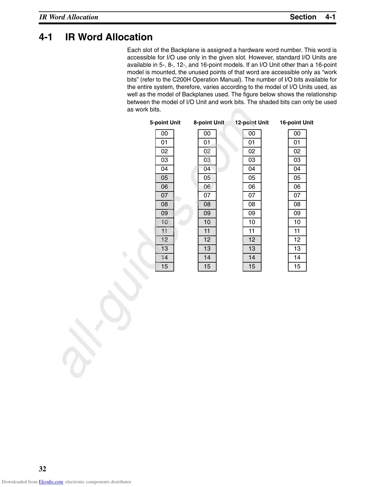
Each
slot of the Backplane is assigned a hardware
word number
. This word is
accessible for I/O use only in the given slot. However, standard I/O Units are
available
in 5-, 8-, 12-, and 16-point models. If an I/O Unit other than a 16-point
model
is mounted, the unused points of that word are accessible only as “work
bits”
(refer to the C200H Operation Manual). The number of I/O bits available for
the
entire system, therefore, varies according to the model of I/O Units used, as
well
as the model of Backplanes used. The figure below shows the relationship
between the model of I/O Unit
and
work bits. The shaded bits can only be used
as work bits.
00
01
02
03
04
00
01
02
03
04
05
06
07
00
01
02
03
04
05
06
07
08
09
10
11
00
01
02
03
04
05
06
07
08
09
10
11
12
13
14
15
5-point Unit 8-point Unit 12-point Unit 16-point Unit
05
06
07
08
09
10
11
12
13
14
15
08
09
10
11
12
13
14
15
12
13
14
15
Downloaded from Elcodis.com electronic components distributor