5-3SectionDuct Work
49
3. Loosen
the screws attaching the Mounting Brackets to the Backplane. Slide
the Backplane upward as shown below so that the Mounting Bracket and
Backplane clamp securely onto the DIN Rail. Tighten the screws.
DIN Rail Mounting Bracket
DIN Rail
Slide this screw to the top of the
projection and then tighten it.
Projections
Hold-down bracket
5-3 Duct
W
ork
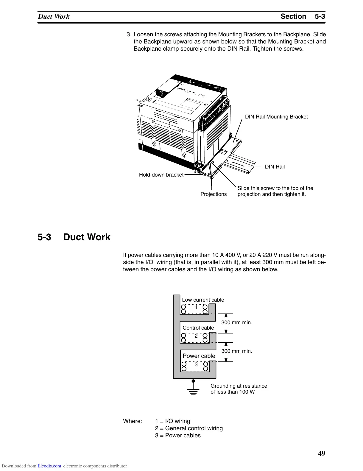
If
power cables carrying more than 10 A 400 V
, or 20 A 220 V must be run along
-
side
the
I/O wiring (that is, in parallel with it), at least 300 mm must be left be
-
tween the power cables and the I/O wiring as shown below.
Low current cable
Control cable
Power cable
300 mm min.
300 mm min.
1
2
3
Grounding at resistance
of less than 100 W
Where: 1 = I/O wiring
2 = General control wiring
3 = Power cables
Downloaded from Elcodis.com electronic components distributor