Appendix EProgramming Instructions
131
IR SR HR TR AR LR TC DM #
00000 to 23515 23600 to 25507 HR 0000 to 9915 TR 0 to 7 AR 0000 to 2715 LR 0000 to 6315 TC 000 to 511 Read/Wr: DM 0000 to DM 0999
Rd only: DM 1000 to DM 1999
0000 to 9999
or 0000 to FFFF
These footnote tables show the actual ranges of all data areas. Bit numbers are provided (except for DM and TC areas); remove the rightmost two digits for word numbers.
Data
Areas
Name
Mnemonic
Operand Data AreasFunctionSymbol
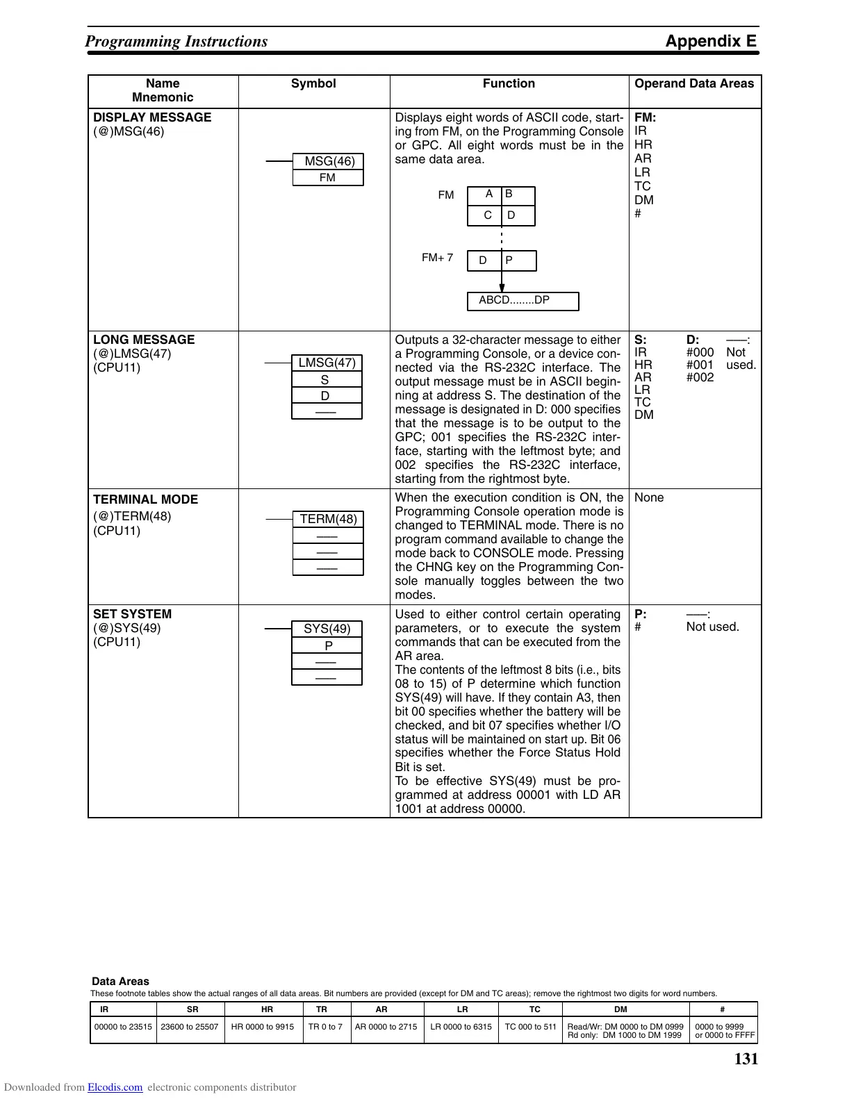
DISPLAY MESSAGE
(@)MSG(46)
MSG(46)
FM
Displays
eight
words of ASCII code, start
-
ing
from FM, on
the Programming Console
or GPC. All eight words must be in the
same
data area.
FM
FM+
7
C D
A B
D P
ABCD........DP
FM:
IR
HR
AR
LR
TC
DM
#
LONG MESSAGE
(@)LMSG(47)
(CPU11)
LMSG(47)
S
D
–––
Outputs
a 32-character message to
either
a
Programming Console, or
a device con
-
nected via the RS-232C interface. The
output message must be in ASCII begin-
ning at address S. The destination of the
message
is designated in
D: 000 specifies
that the message is to be output to the
GPC; 001 specifies the RS-232C inter-
face, starting with the leftmost byte; and
002 specifies the RS-232C interface,
starting from the rightmost byte.
S:
IR
HR
AR
LR
TC
DM
D:
#000
#001
#002
–––:
Not
used.
TERMINAL MODE
(@)TERM(48)
(CPU11)
TERM(48)
–––
–––
–––
When the execution condition is ON, the
Programming Console operation mode is
changed
to TERMINAL mode.
There is no
program
command available to change the
mode back to CONSOLE mode. Pressing
the CHNG key on the Programming Con-
sole manually toggles between the two
modes.
None
SET SYSTEM
(@)SYS(49)
(CPU11)
SYS(49)
P
–––
–––
Used to either control certain operating
parameters, or to execute the system
commands
that can be executed from the
AR area.
The
contents of the leftmost 8
bits (i.e., bits
08 to 15) of P determine which function
SYS(49)
will have. If they contain A3,
then
bit
00 specifies whether the
battery will be
checked,
and bit 07 specifies whether
I/O
status
will be maintained on start up. Bit 06
specifies whether the Force Status Hold
Bit is set.
To be effective SYS(49) must be pro-
grammed at address 00001 with LD AR
1001 at address 00000.
P:
#
–––:
Not used.
Downloaded from Elcodis.com electronic components distributor