2-6SectionMemory Units
20
The data that you wish to store in an EPROM Unit must first be written to an
EPROM
Chip, using the PROM W
riter
. Then the EPROM Chip must be mounted
to
the inside of the EPROM Unit. Once this has been done, the data cannot be
changed. In addition, the data will be retained indefinitely when the power is
turned OFF.
Data
can be stored in the EEPROM Unit while the
Unit is mounted to the PC. The
data is retained indefinitely when the power is turned OFF.
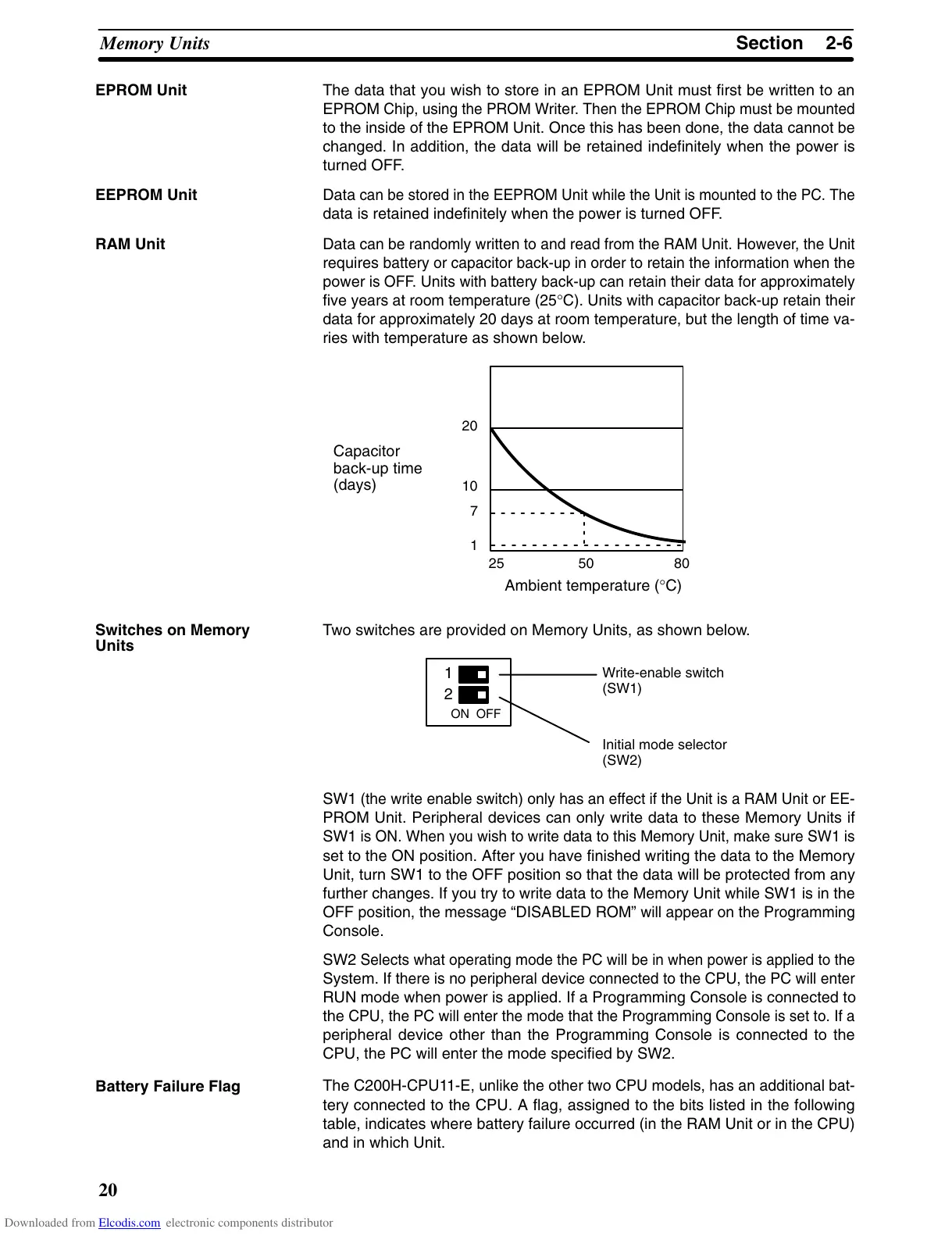
Data
can be randomly written to and read from the RAM Unit. However
, the
Unit
requires
battery or capacitor back-up in order to
retain the information when the
power
is OFF
. Units with battery back-up can
retain their data for approximately
five
years at room temperature (25
°
C). Units with capacitor back-up retain their
data
for approximately 20 days at room temperature, but the length of time va
-
ries with temperature as shown below.
20
10
7
1
25 50 80
Ambient temperature (°C)
Capacitor
back-up time
(days)
Two switches are provided on Memory Units, as shown below.
1
2
ON OFF
Write-enable switch
(SW1)
Initial mode selector
(SW2)
SW1
(the write enable switch) only has an ef
fect if the Unit is a RAM Unit or EE
-
PROM Unit. Peripheral devices can only write data to these Memory Units if
SW1
is ON. When you wish to write
data to this Memory Unit, make sure SW1 is
set to the ON position. After you have finished writing the data to the Memory
Unit, turn SW1 to the OFF position so that the data will be protected from any
further
changes. If you try to write data to the Memory Unit while SW1 is in the
OFF
position, the message “DISABLED ROM”
will appear on the Programming
Console.
SW2
Selects what operating mode the PC will be
in when power is applied to the
System.
If there is no peripheral device connected to the CPU, the PC will enter
RUN mode when power is applied. If a Programming Console is connected to
the
CPU, the PC will enter
the mode that the Programming Console is set to. If a
peripheral device other than the Programming Console is connected to the
CPU, the PC will enter the mode specified by SW2.
The
C200H-CPU1
1-E, unlike the other two CPU models, has an additional
bat
-
tery connected to the CPU. A flag, assigned to the bits listed in the following
table,
indicates where battery failure occurred (in the RAM Unit or in the CPU)
and in which Unit.
EPROM Unit
EEPROM Unit
RAM Unit
Switches on Memory
Units
Battery Failure Flag
Downloaded from Elcodis.com electronic components distributor