Appendix BSpecifications
118
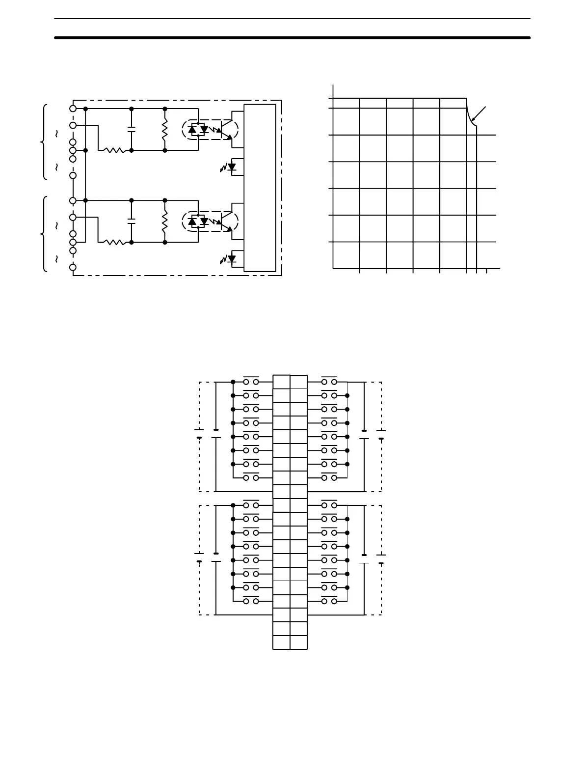
Circuit Configuration and Simultaneously Usable Points
Input indicator
Input indicator
Input Voltage: 26.4 VDC
Ambient Temperature (°C)
Simultaneously Usable Points
0 10203040505560
0
5
10
15
20
25
30
32
1000 pF
680 Ω
5.6 kΩ
COM
IN00
IN07
COM
IN08
IN15
A
Internal
circuit
COM
IN00
IN07
COM
IN08
IN15
B
1000 pF
680 Ω
5.6 kΩ
Terminal Connections
I/O word “m” I/O word “m+1”
0
1
1
2
2
3
3
4
4
5
5
6
6
7
7
8
COM
9
A
24 VDC
0
1
1
2
2
3
3
4
4
5
5
6
6
7
7
8
COM
9
B
+
+
24 VDC
8
10
9
11
10
12
11
13
12
14
13
15
14
16
15
17
COM
18
8
10
9
10
11
12
13
14
15
COM
+
+
24 VDC 24 VDC
11
12
13
14
15
16
17
18
NC
19
NC
20
NC
19
NC
20
Note 1. I/O word “m” is determined by the I/O number setting (m = IR 030 + 2 × I/O number).
2. The power can be supplied in either polarity, but the same polarity must be used for all COM terminals.
Connect power supply wiring to every COM terminal, even though the COM terminals are connected
internally.
Artisan Technology Group - Quality Instrumentation ... Guaranteed | (888) 88-SOURCE | www.artisantg.com