Appendix BSpecifications
127
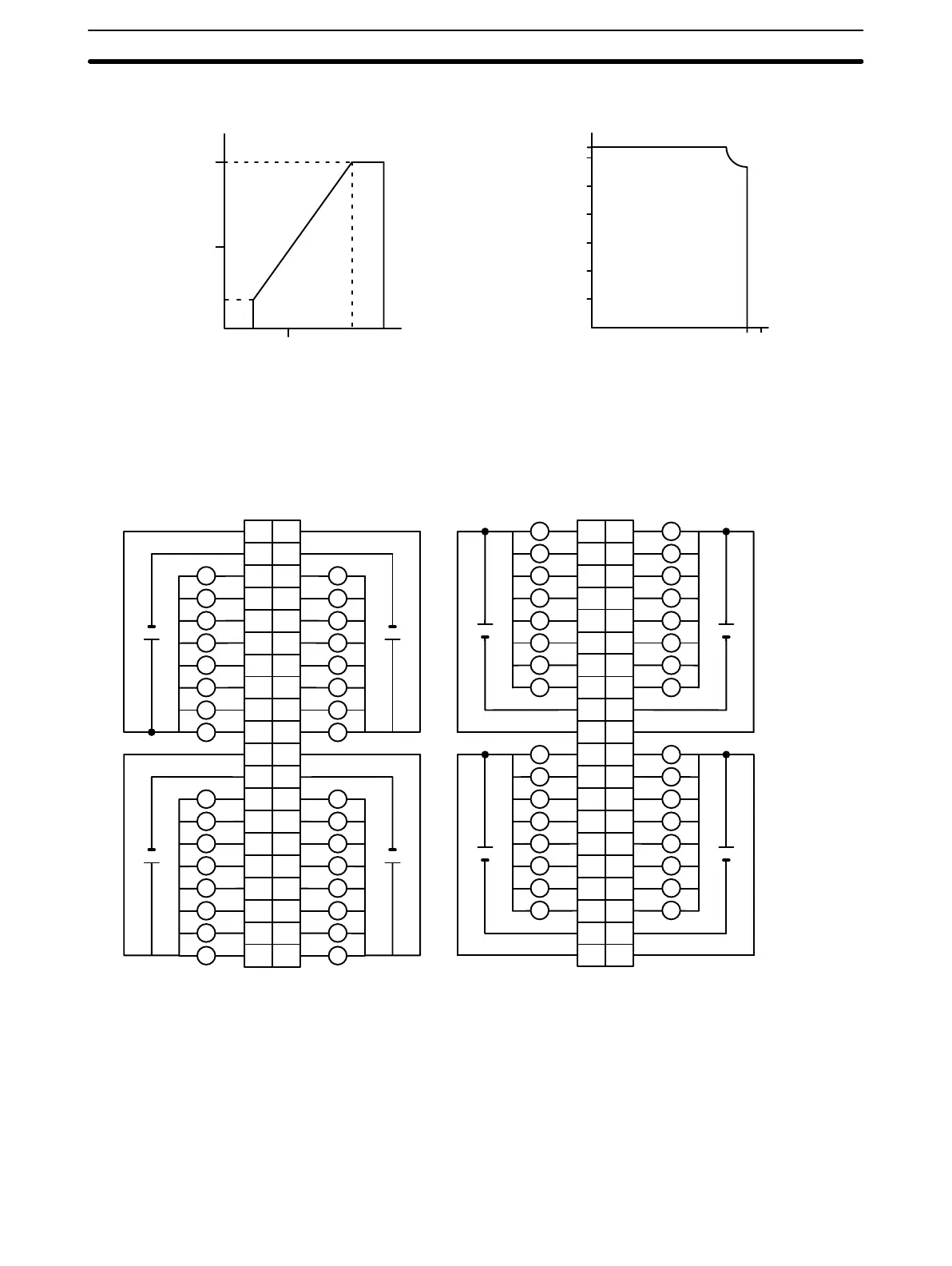
Maximum Switching Capacity
Power Supply Voltage (V)
Max. Switching Capacity (mA/pt)
Max. Switching Capacity (A/unit)
Ambient Temperature (°C)
0 4.5 10 20.4 26.4
50
100
16
0
0 10203040505560
0
1.0
2.0
3.0
4.0
5.0
6.0
6.4
Terminal Connections
I/O word “m”I/O word “m+1”
CN1
I/O word “m+3”I/O word “m+2”
CN2
L
L
1
0
B
1
2
2
3
3
4
4
5
5
6
6
7
7
8
9
0
1
2
3
4
5
6
7
COM
A
+
COM
+
10
11
12
13
14
15
16
18
19
20
17
8
9
10
11
12
13
14
15
COM
+
8
9
10
11
12
13
14
15
COM
+
1
2
3
4
5
6
7
8
9
10
11
12
13
14
15
16
18
19
20
17
L
L
L
L
L
L
L
L
L
L
L
L
L
L
L
L
L
L
L
L
L
L
L
L
L
L
L
L
L
1L
0
A
1
2
2
3
3
4
4
5
5
6
6
7
7
8
9
0
1
1
2
2
3
3
4
4
5
5
6
6
7
7
8
COM
9
B
L
L L
L L
L L
L L
L L
L L
L L
+
COM
+
10 10
11
12
13
14
15
16
18
11
12
13
14
15
16
17
18
19
20
19
20
17
8
9
10
11
12
13
14
15
COM
L
L
L
L
L
L
L
L
+
8
9
10
11
12
13
14
15
COM
L
L
L
L
L
L
L
L
+
4.5 to
26.4 VDC
L
Note 1. I/O word “m” is determined by the I/O number setting (m = IR 030 + 2 × I/O number).
2. When either fuse blows, the F indicator lights and the error flag in AR 02 corresponding to the I/O number
is turned ON. I/O numbers 0 to 9 correspond to AR 0205 to AR 0214.
3. The interruption of power from the external power supply is treated the same as a fuse blowout.
4. Connect power supply wiring to every COM terminal, even though the COM terminals in each connector
are connected internally.
5. When wiring output circuits, be sure to use the correct polarity for the external power supplies. Wiring
with incorrect polarity may result in erroneous operation of the load.
Artisan Technology Group - Quality Instrumentation ... Guaranteed | (888) 88-SOURCE | www.artisantg.com