Appendix BSpecifications
136
3. Set pin 5 of the Unit’s DIP switch ON for positive logic outputs, or OFF for negative logic outputs. When
set for negative logic outputs, the terminal has an “L” voltage level when there is an output. When set for
positive logic outputs, the terminal has an “H” voltage level when there is an output.
4. The strobe signal has negative logic regardless of the setting of pin 5.
5. Each output terminal has an output resistance of 4.7 kΩ.
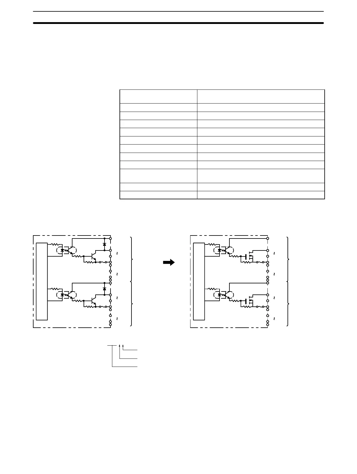
Transistor Output Unit C200H-OD215 (Used as 32-point Output Unit)
Max. Switching Capacity 16 mA 4.5 VDC to 100 mA 26.4 VDC (see below)
800 mA/common, 3.2 A/Unit
Min. Switching Capacity None
Leakage Current 0.1 mA max.
Residual Voltage 0.7 V max.
ON Response Time 0.2 ms max.
OFF Response Time 0.6 ms max.
No. of Circuits 4 (8 points/common)
Internal Current Consumption 220 mA 5 VDC max.
Fuses 4 (1 fuse/common; fuses are not user-replacable.)
Power for External Supply 90 mA 5 to 24 VDC±10% min.
(2.8 mA × number of ON outputs)
Weight 300 g max.
Dimensions 130×34.5×100.5 (H×W×D, in millimeters)
Circuit Configuration
Units manufactured on or before November 29th, 1999
(manufacturing numbers 29Y9 or earlier*)
Units manufactured on or after November 30th, 1999
(manufacturing numbers 30Y9 or later*)
OUT00
OUT07
COM0
OUT08
OUT15
COM1
Inter-
nal
Cir-
cuit
Fuse
Fuse
CN1
5 to
24 VDC
5 to
24 VDC
OUT00
OUT07
COM2
OUT08
OUT15
COM3
CN2
5 to
24 VDC
5 to
24 VDC
OUT00
OUT07
COM0
OUT08
OUT15
COM1
Inter-
nal
Cir-
cuit
Fuse
Fuse
CN1
5 to
24 VDC
5 to
24 VDC
OUT00
OUT07
COM2
OUT08
OUT15
COM3
CN2
5 to
24 VDC
5 to
24 VDC
10 kΩ
10 kΩ
8.2 kΩ
8.2 kΩ
15 kΩ
6.8 kΩ
15 kΩ
6.8 kΩ
*Manufacturing Numbers
jjY9
Year: Last digit of calendar year; e.g., 1999→9, 2000→0
Month: 1 to 9 (January to September), X (October), Y (November), Z (December)
Day: 01 to 31
Artisan Technology Group - Quality Instrumentation ... Guaranteed | (888) 88-SOURCE | www.artisantg.com