Appendix BSpecifications
140
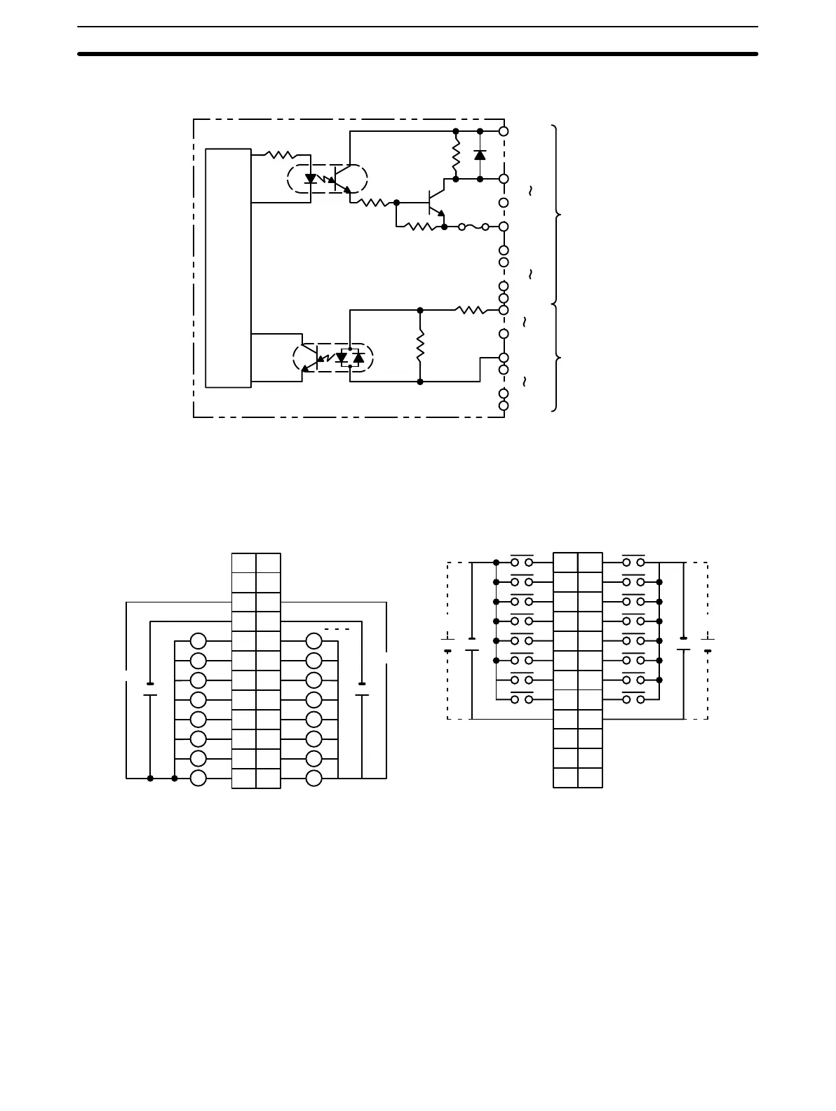
Circuit Configuration
CN1 (Output)
CN2 (Input)
OUT00
OUT07
COM0
OUT08
OUT15
COM1
Internal
circuit
5 VDC
5 VDC
Fuse
4.7 kΩ
COM2
IN08
IN15
COM3
IN00
IN07
1.1 kΩ
2.4 kΩ
Terminal Connections
I/O word “n”
CN1
I/O word “n+1”
CN2
AB
0
1
1
2
2
3
3
4
4
5
5
6
6
7
7
8
COM2
9
8
9
10
11
12
13
14
15
COM3
+
+
NC
10
NC
11
NC
NC
NC
12
NC
+
5 VDC
1
2
3
4
5
6
7
8
9
10
11
12
+
5 VDC
L
+5 VDC +5 VDC
B
1
2
3
4
5
6
7
8
9
0
1
2
3
4
5
6
7
COM0
+
10
NC
11
NC
8
9
10
11
12
13
14
15
COM1
+
NC
12
A
1
2
3
4
5
6
7
8
9
10
11
12
NC
5 VDC
5 VDC
L
L
L
L
L
L
L
L
L
L
L
L
L
L
L
Note 1. I/O word “n” is determined by the unit number setting (n = IR 100 + 10 × unit number).
2. The Unit will have 16 static output and16 static input points when pin 1 of it’s DIP switch is OFF.
3. When pin 2 of the Unit’s DIP switch is ON, input points 08 to 15 in connector 2 are high-speed inputs.
4. The outputs are negative logic outputs; when there is an output, the terminal has an “L” voltage level.
Each output terminal has an output resistance of 4.7 kΩ.
5. The user is not authorized to change the fuse.
Artisan Technology Group - Quality Instrumentation ... Guaranteed | (888) 88-SOURCE | www.artisantg.com