Appendix BSpecifications
149
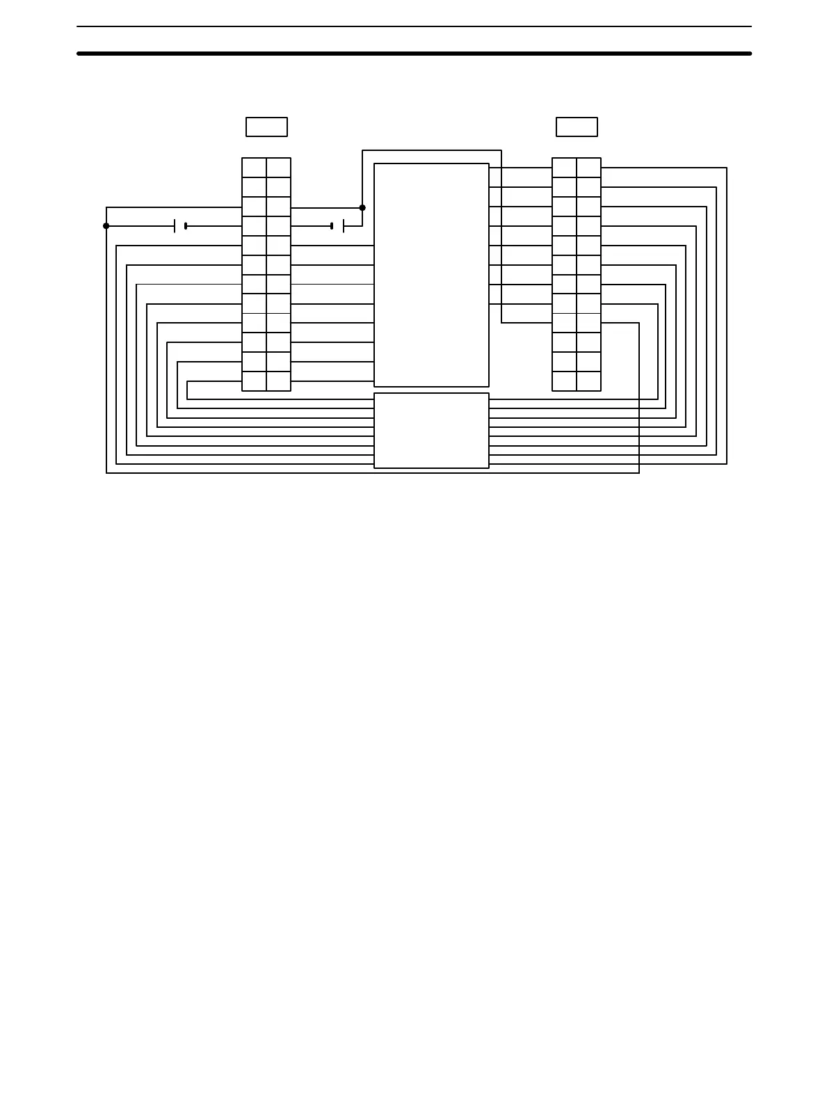
Terminal Connections
12 VDC
STB8
STB9
STB10
STB11
STB12
STB13
STB14
STB15
DATA8
A
1
2
3
4
5
6
7
8
9
DATA0
DATA1
DATA2
DATA3
DATA4
DATA5
DATA6
DATA7
COM2
NC
10
NC
11
NC
NC
NC
12
B
1
2
3
4
5
6
7
8
9
10
11
12
NC
CN2
A
1
2
3
4
5
6
7
8
9
COM1
+V0
10
NC
11
+V1
NC
STB0
STB1
STB2
STB3
STB4
STB5
STB6
STB7
COM0
NC
12
B
1
2
3
4
5
6
7
8
9
10
11
12
NC
CN1
DATA9
DATA10
DATA11
DATA12
DATA13
DATA14
DATA15
COM3
+ +
12 VDC
Keyboard, thumb-
wheel switch, etc.
Keyboard, thumb-
wheel switch, etc.
Note 1. Refer to the Unit’s Operation Manual for details on I/O bit allocation.
2. The Unit will have 128 dynamic output points when pin 1 of it’s DIP switch is ON.
3. Each output terminal has an output resistance of 4.7 kΩ.
4. At high temperatures, the number of inputs that can be turned ON simultaneously is limited. Refer to the
graph on page 150 for details.
5. The user is not authorized to change the fuse.
6. When wiring output circuits, be sure to use the correct polarity for the external power supplies. Wiring
with incorrect polarity may result in erroneous operation of the load.
High-density I/O Unit Limitations
Limitations on the switching capacity of C200H-OD215/MD115/MD215 Transistor Output Units and the usable
number of I/O points in the C200H-ID215 and C200H-MD215 are shown below.
Switching Capacity
The switching capacity of C200H-OD215/MD115/MD215 Transistor Output Units depends on the power supply
voltage, as shown below.
Artisan Technology Group - Quality Instrumentation ... Guaranteed | (888) 88-SOURCE | www.artisantg.com