50
Where
E
on
= ON voltage of the load
I = leakage current in mA
R = bleeder resistance
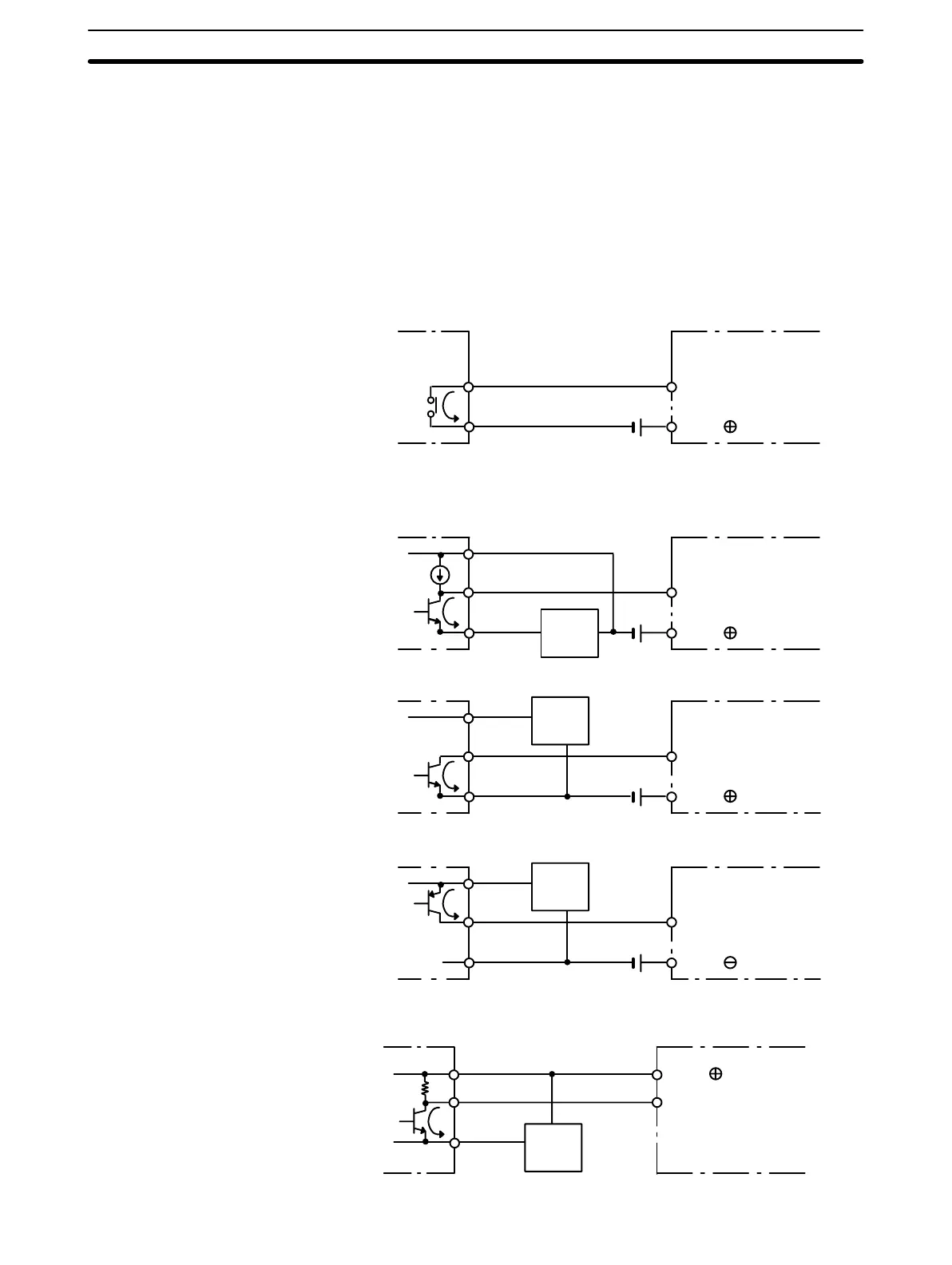
Wiring Examples The following are examples of how to connect I/O devices to I/O Units. During
wiring, work slowly and carefully. If an input device is connected to an Output
Unit, damage may result. Check all I/O devices to make sure they meet the spec-
ifications (refer to Appendix B Specifications).
DC Input Units
COM
Contact output
IN DC input
When using the NPN-current-output configuration shown below, the sensor and
Input Unit should receive their power from the same supply.
+
COM
NPN current output
IN DC input
0 V
Output
7 mA
Sensor
Power
Supply
Current
regulator
+
COM
NPN open-collector output
Sensor
Power
Supply
IN DC input
0 V
Output
7 mA
+
COM
PNP current output
Sensor
Power
Supply
IN AC/DC input
0 V
Output
7 mA
0 V
The circuit below should be used for I/O devices having a voltage output.
0 V
Output
+
COM
Voltage output
Sensor
Power
Supply
IN DC input
I/O Connections Section 4-4
Artisan Technology Group - Quality Instrumentation ... Guaranteed | (888) 88-SOURCE | www.artisantg.com