6. Serial Communications Settings
6.2. Cable Wiring Diagram
For details on the cable wiring, refer to Section 3 Installation and Wiring of the CJ-series Serial
Communications Boards and Serial Communications Units Operation Manual (Cat.No. W336)
and Section 4 Diagnosis and Maintenance-Wiring for cable of V750-series UHF RFID
System User’s Manual(Cat.No. Z235). Check the connector configuration and pin assignment
for wiring.
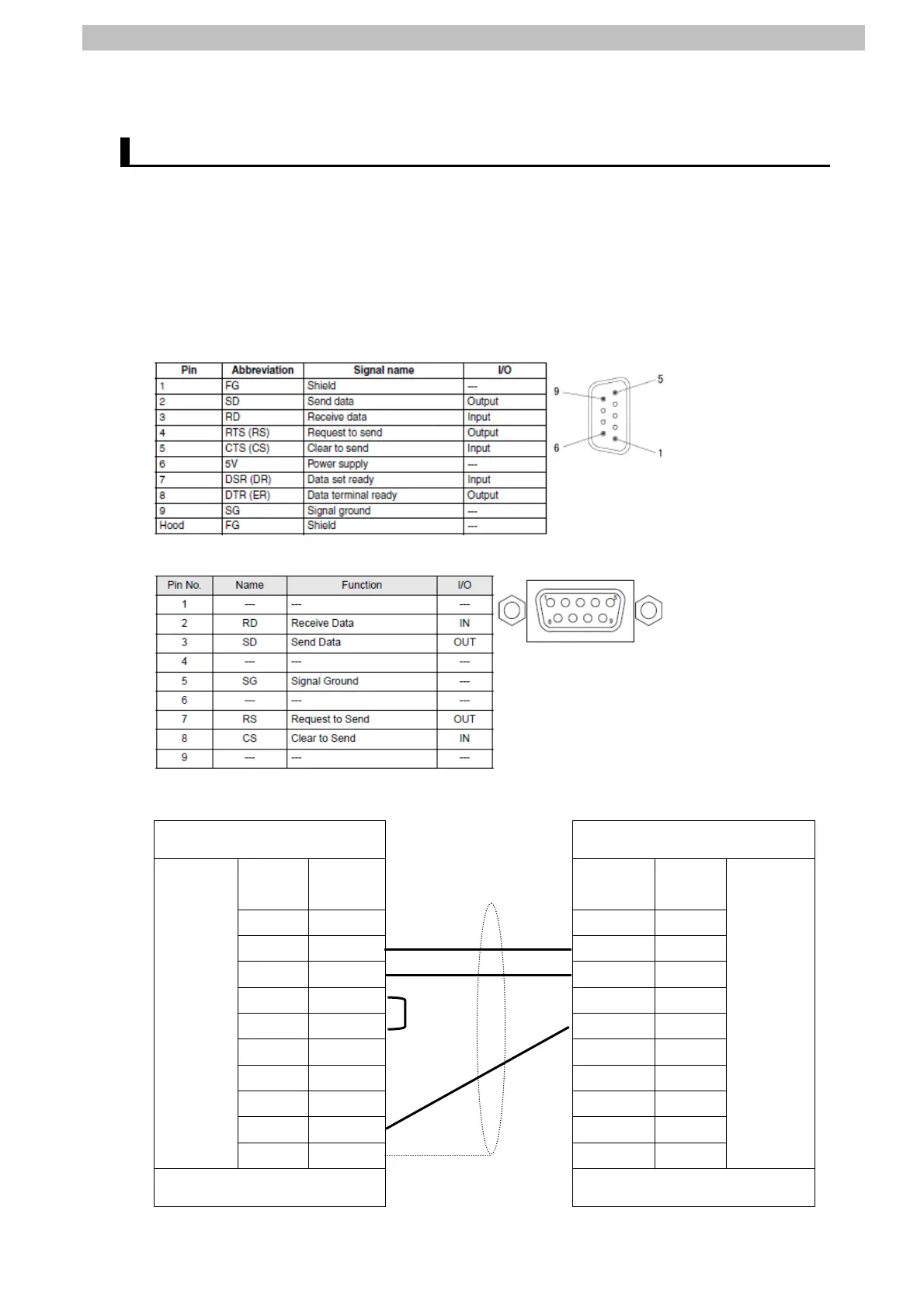
■Connector configuration and pin assignment
<OMRON CJ1W-SCU42> Applicable connector: D-sub 9 pin
<OMRON V750-BA50C04-US> Applicable connector: D-sub 9 pin
■Cable/Pin arrangement
Serial Communications Unit
(CJ1W-SCU42)
RFID Reader/Writer
(V750-BA50C04-US)
Signal
name
Pin No. Pin No. Signal
name
FG 1 1
SD 2 2 RD
RD 3 3 SD
RS 4 4
CS 5 5 SG
5V 6 6
DR 7 7 RS
ER 8 8 CS
SG 9 9
RS-232C
interface
FG Shell Shell
RS-232C
interface
D-sub 9-pin
Cable connector type: Male
D-sub 9-pin
Cable connector type: Female
11