108
Wiring Section 3-3
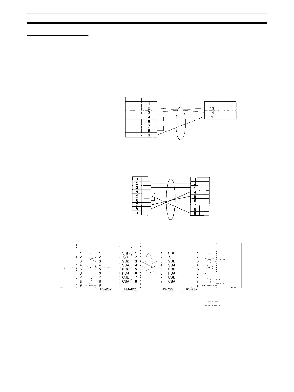
Connection Examples
The connection examples in the remainder of this section show only the basic
connection diagrams. We recommend that appropriate noise countermea-
sures be taken in actual applications, including the use of shielded twisted-
pair cables. Refer to 3-4 RS-232C and RS-422A/485 Wiring for actual wiring
methods.
Connecting RS-232C Ports 1:1
Connections to E5CK Controller
Connections to a Personal Computer with RTS-CTS Flow Control
Connecting a Host Computer with NT-AL001-E Converting Link Adapters
Serial Communications
Unit or Board
RS-232C
Shield
OMRON E5CK Controller
RS-232C: Terminal Block
Terminal
Signal Pin
Signal
D-sub, 9-pin
connector (male)
FG
SD
RD
RTS
CTS
DSR
DTR
SG
SD
RD
SG
Computer
Serial Communications
Board or Unit
RS-232C port
FG
SD
RD
RTS
CTS
DSR
DTR
SG
FG
SD
RD
RTS
CTS
5V
DSR
DTR
SG
5-V (+)
power (-)
NT-AL001-E Link Adapter
RS-232C
Interface
RS-232C
Interface
Signal
Pin
DIP Switch Settings
Pin 1: ON
Pin 2: ON
(terminating resistance)
Pin 3: OFF (4-wire)
Pin 4: OFF
Pin 5: OFF
Pin 6: OFF
NT-AL001-E Link Adapter
RS-232C
PinPinPin
Signal
SignalSignal Signal
Serial Communications
Board or Unit
Computer
RS-422A
(See note)
D-sub, 9-pin
connector (male)
DIP Switch Settings
Pin 1: ON
Pin 2: ON
(terminating resistance)
Pin 3: OFF (4-wire)
Pin 4: OFF
Pin 5: OFF
Pin 6: ON
D-sub, 9-pin
connector (male)
Terminal block
Shield
RS-232C
Signal Pin
FG
SD
RD
RTS
CTS
DSR
DTR
SG
FG
SD
RD
RTS
CTS
5V
DSR
DTR
SG
NC
SD
RD
RTS
CTS
5V
DSR
DTR
SG
NC
SD
RD
RTS
CTS
5V
DSR
DTR
SG
 Loading...


