304
Executing Loopback Tests Section 10-1
10-1 Executing Loopback Tests
10-1-1 Overview
Executing a loopback test will allow you to test a port communications circuit
by connecting a loopback-wire connector to the port of a Serial Communica-
tions Board or Unit, looping back the transmitted data to make it the received
data for the Unit or Board, and then comparing and checking the data.
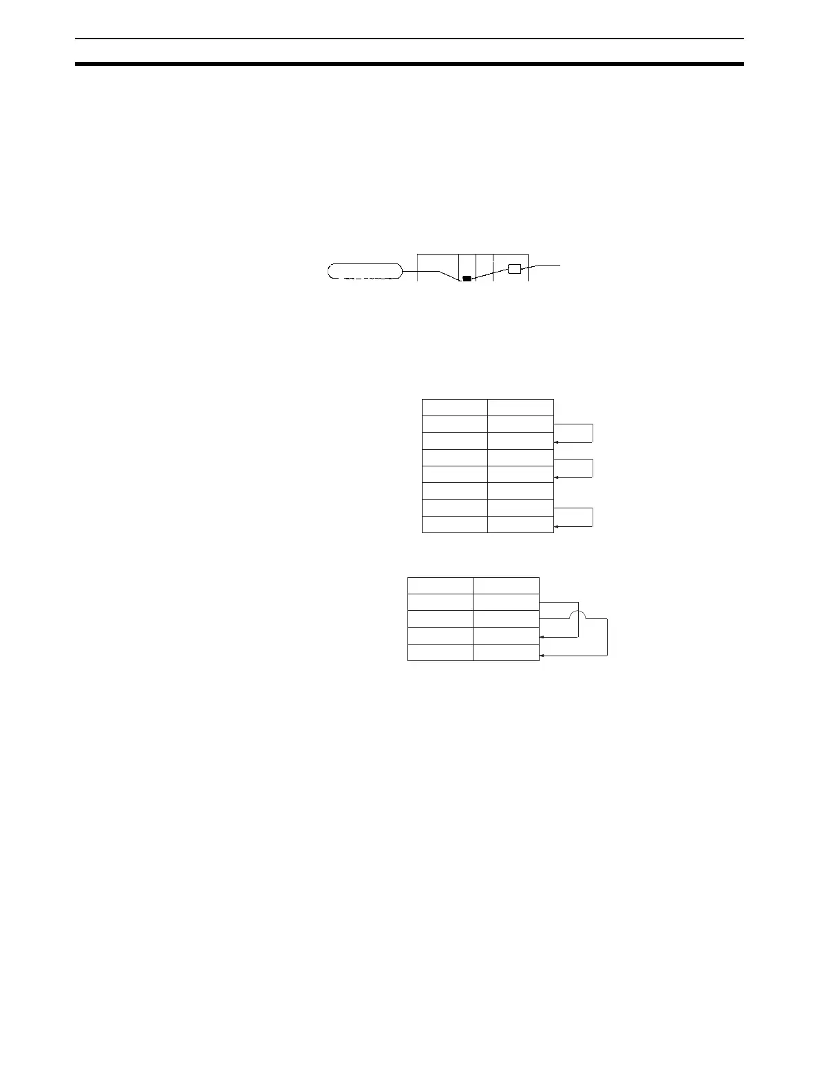
10-1-2 Connection Method
Make the connections according to the type of port, as shown in the following
diagrams.
RS-232C Port
RS-422A/485 Port
10-1-3 Procedure
The loopback test is performed using the procedure shown below.
1,2,3... 1. Connect the connector of the port to be used to execute the loopback test.
See
10-1-2 Connection Method for details.
2. Set the serial communications mode in the Setup Area to Loopback Test
(F Hex). Refer to
10-2 Setup Area Allocations.
3. Set the following communications settings for the loopback test in the Set-
up Area: Baud rate, stop bits, parity, and data length. Refer to
10-2 Setup
Area Allocations
.
4. Cycle the power, restart the Unit or Board, or restart the port.
Use the following bits to restart the Board or Unit.
Board: A60800
Units: A501, bits 00 to 15 (bits correspond to unit numbers 0 to F)
Use the following bits to restart the port.
Board: A636, bit 01 for port 1 and bit 02 for port 2
Units: A620 + unit number, bit 01 for port 1 and bit 02 for port 2
Loopback test
Loopback test switch
Serial Communications Unit
(CS/CJ Series)
Pin
Signal
2
3
4
5
1
8
7
SD
RD
RTS
CTS
FG
DTR
DSR
Pin
Signal
1
2
6
8
SDA
SDB
RDA
RDB
 Loading...


