190
Enhanced Protocol Macro Functions Section 5-6
If the restore operation fails, the RDY Indicator will continue to flash. The CPU
Unit’s ERR/ALM Indicator will flash and bit A42409 (the Protocol Data Error
Flag) will be turned ON.
Serial Communications Unit Operation
The Serial Communications Unit’s RDY Indicator will flash during the restore
operation. Both the RDY Indicator and RUN Indicator will be lit when the
restore operation is completed normally.
If the restore operation fails, the RDY Indicator will continue to flash and the
ERC Indicator will be lit.
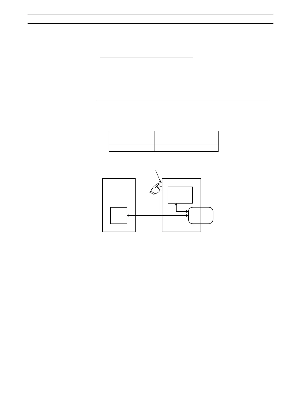
■ Comparing the Protocol Data with the Memory Card’s Protocol Data File
Follow these steps to compare the Serial Communications Board/Unit’s proto-
col data with the Protocol Data File in the Memory Card:
1. Make the following settings to pins 7 and 8 in the DIP Switch on the front
of the CPU Unit.
2. Press and hold the Memory Card power supply switch for 3 seconds.
This procedure compares the protocol data in the Serial Communications
Board/Unit with the data in the Protocol Data File in the CPU Unit’s Memory
Card.
When the Memory Card power supply switch is pressed, the MCPWR Indica-
tor on the front of the CPU Unit will flash once and then remain lit while the
data is being compared. If the data matches, the Indicator will go OFF after
the data has been compared.
5-6 Enhanced Protocol Macro Functions
Serial Communications Boards/Units with Unit Ver. 1.2 or later support the fol-
lowing enhanced protocol macro functions.
• Data exchange timing in link word specification
• Selection to clear or hold the contents of the reception buffer during full-
duplex communications
• High-speed baud rate in protocol macro mode
Pin Setting
7OFF
8OFF
Serial Communications
Board/Unit
Protocol data
• Compare
Memory Card power supply switch
CPU Unit
All data
Memory Card
 Loading...


