216
Protocol Conversion Section 6-5
(2) The contents of the CompoWay/F command enclosed in the FINS mes-
sage that is sent is as follows:
Node number + subaddress + SID + command text (ASCII must be used.)
STX, ETX+BCC are not required when sending FINS. They are added
automatically for serial communications.
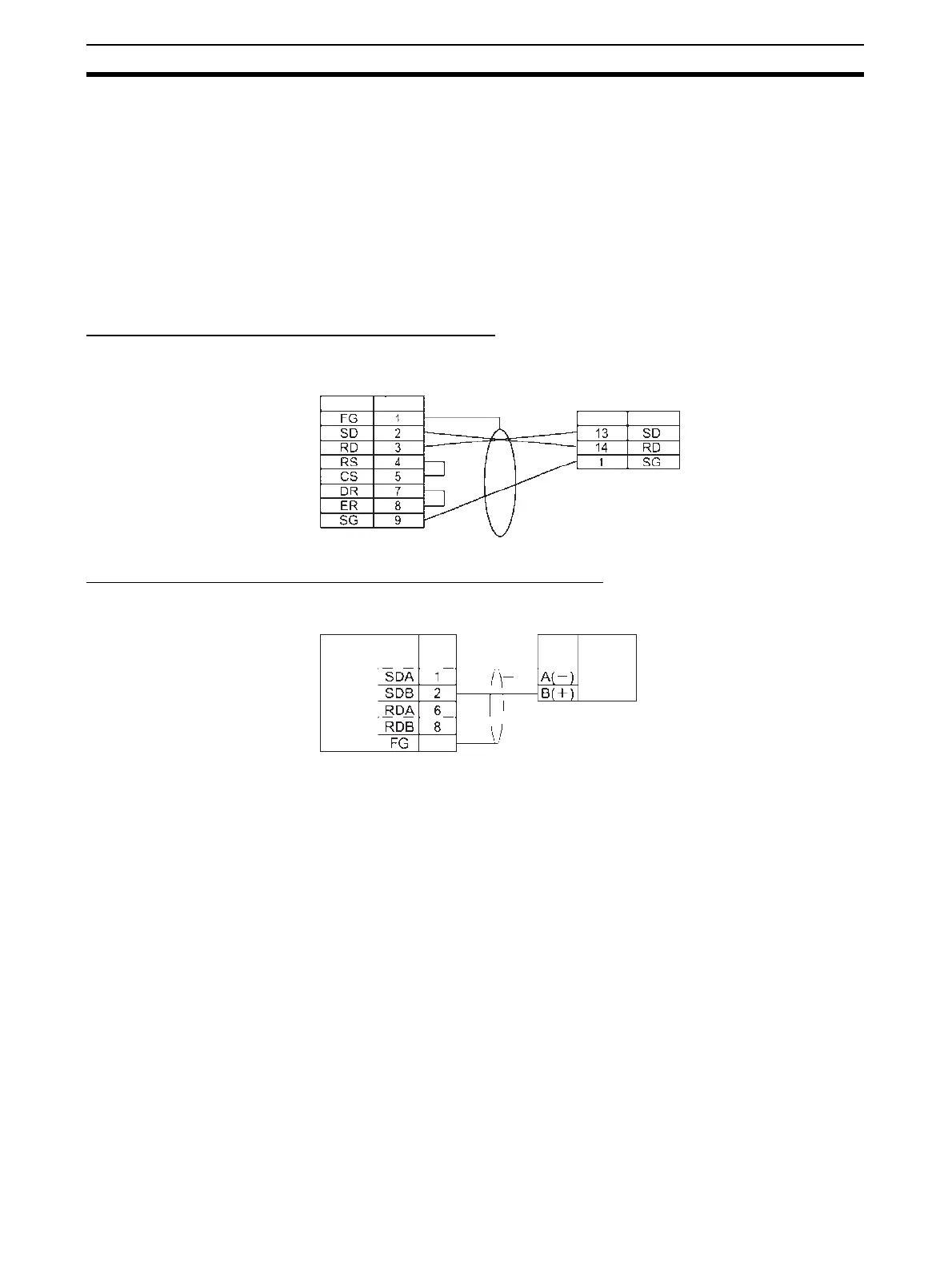
6-5-3 CompoWay/F Connection Examples
Connection diagrams are provided here. OMRON recommends the use of
shielded twisted-pair cables for actual wiring to enhance noise resistance. For
details on wiring methods, refer to
3-4 RS-232C and RS-422A/485 Wiring.
1:1 Connection Example Using RS-232C Port
Connection Example with E5CK Digital Controller
1:1 RS-485 Connection Example Using RS-422A/485 Port
Note Be sure to connect terminating resistance of between 100 and 125 Ω (1/2 W)
to the terminals of the remote devices at either end of the RS-422A/485 trans-
mission path. (Set the terminating resistance on the Board/Unit by turning
ON/OFF the Terminating Resistance Switch.)
Signal name
Pin No.
Serial Communications Unit/Board
RS-232C shield wire
Example: E5CK (OMRON Digital Controller)
RS-232C: Terminal Block
Terminal No. Signal name
D-Sub 9-pin (Cable connector type: Male)
Serial Communications Board/Unit
Pin No.
Shell
Shield wire
D-Sub 9-
in
Cable connector t
e: Male
RS-422A/485
interface
Signal
name
Signal
name
RS-422A/485
interface
Component with RS-422A/485
communications function
(2-wire method)
 Loading...


