286
Auxiliary Area and CIO Area Allocations (Modbus-RTU Slave Mode) Section 9-3
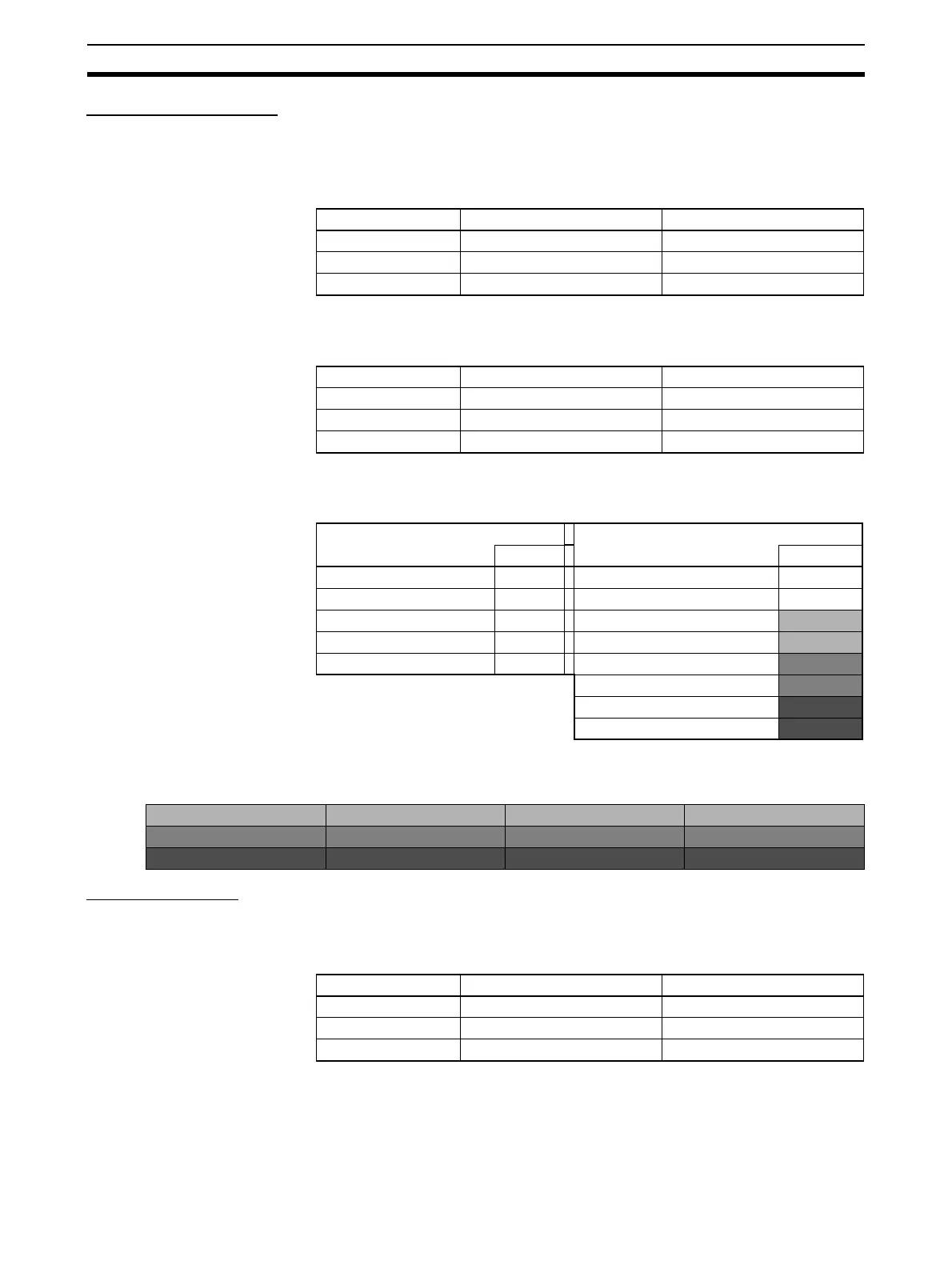
Read Input Registers
Function Reads multiple words from the CIO, Work, Holding, or Auxiliary Area of I/O
memory.
Command
Note The address depends on the area that is allocated.
Response
Note N = Quantity of Registers
Reading 3 Words from
D1000 to D1002
Write Single Coil
Function Writes a bit in I/O memory.
Command
Note The address depends on the area that is allocated.
Length Data
Function Code 1 byte 04 hex
Starting Address 2 bytes 0 to 17FF hex (See note.)
Quantity of Registers 2 bytes 1 to 7D hex
Length Data
Function Code 1 byte 04 hex
Byte Count 1 byte N × 2 (See note.)
Register Value N × 2 bytes
Request Response
Data Data
Function Code 04 hex Function Code 04 hex
Starting Address (H) 03 hex Byte Count 06 hex
Starting Address (L) E8 hex Register Value (H) DM1000 AB hex
Quantity of Registers (H) 00 hex Register Value (L) DM1000
12 hex
Quantity of Registers (L) 03 hex Register Value (H) DM1001
56 hex
Register Value (L) DM1001
78 hex
Register Value (H) DM1002
97 hex
Register Value (L) DM1002
13 hex
1514131211109876543210
D1000
A B 1 2
D1001
5 6 7 8
D1002
9 7 1 3
Length Data
Function Code 1 byte 05 hex
Output Address 2 bytes 0 to FFFF hex (See note.)
Output Value 2 bytes 0000 hex (OFF) or FF00 (ON)
 Loading...


