671
Visual Inspection System Protocol Appendix O
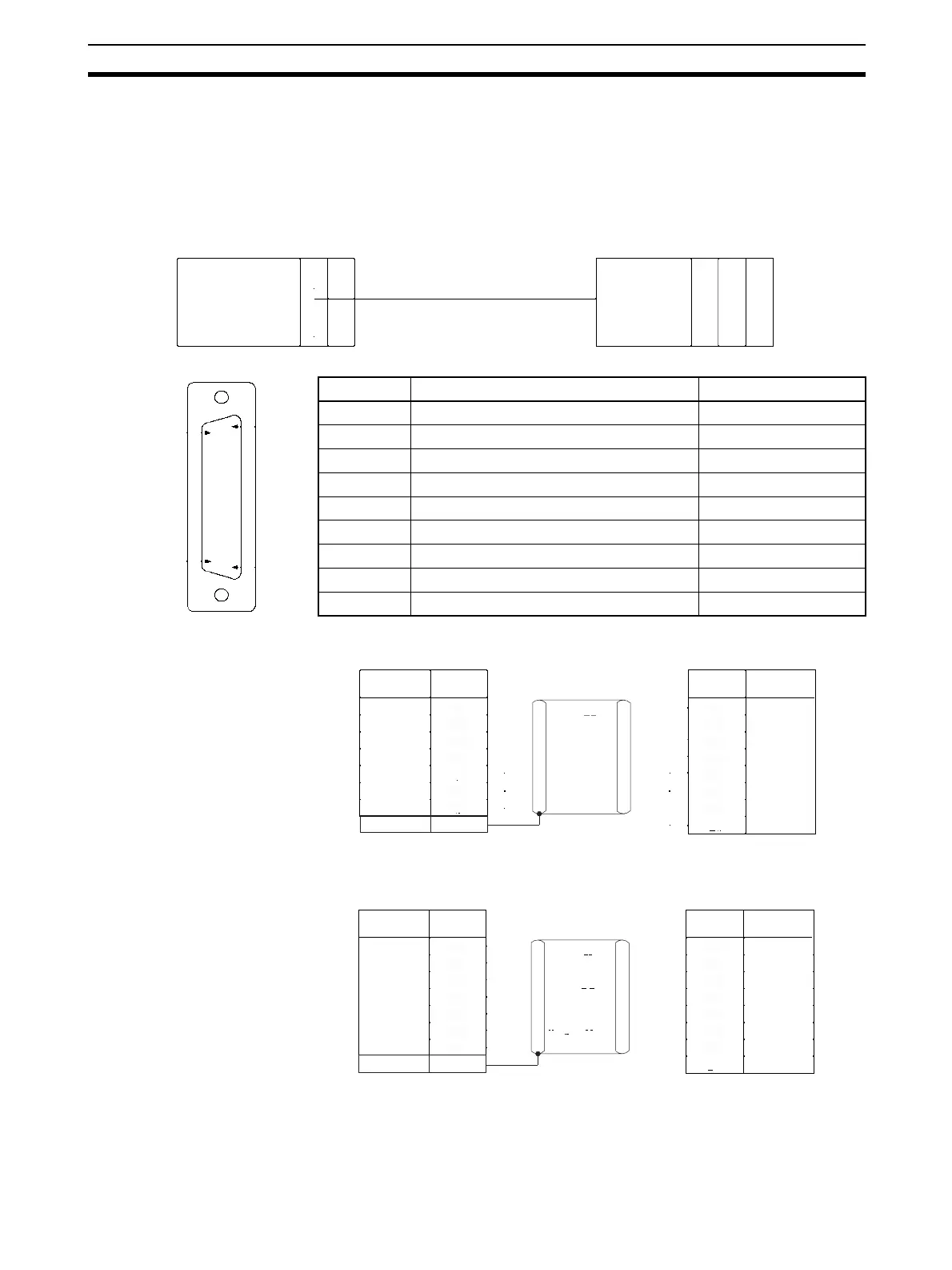
Connections
The connections for using the Visual Inspection System Protocol are shown below.
RS-232C Connections
• For RS/CS Flow Control
Pin No. Signal name Abbreviation
1 Protective ground or earth FG (GND)
2 Send data SD (TXD)
3 Receive data RD (RXD)
4 Request to send RS (RTS)
5 Clear to send CS (CTS)
6 Data set ready DR (DSR)
7 Signal ground SG (GND)
8 Carrier detection (Data word receive) CD (DCD)
20 Data terminal ready
ER (DTR)
RS-232C port
RS-232C Unit
→
F200/300/350
RS-232C
Serial Communications Board
(CS Series only)
Serial Communications Unit
(CS/CJ Series)
PLC
PS
25
14
13
1
Serial Communications Unit/
Board: D-sub 9 pin (female)
Signal Name Signal NamePin No. Pin No.
F300-E:
D-sub 25 pin (female)
1
SD (TXD)
RD (RXD)
RTS
CTS
DSR
SG
DTR
FG
SD (TXD)
RD (RXD)
RTS
CTS
DSR
SG
CD (DCD)
DTR
2
3
4
5
7
9
8
20
2
3
4
5
6
7
8
Signal Name Signal NamePin No. Pin No.
Serial Communications Unit/
Board: D-sub 9 pin (female)
F300-E:
D-sub 25 pin (female)
1
SD (TXD)
RD (RXD)
RTS
CTS
DSR
SG
DTR
FG
SD (TXD)
RD (RXD)
RTS
CTS
DSR
SG
CD (DCD)
DTR
2
3
4
5
7
9
8
2
3
4
5
6
7
8
20
 Loading...


