TL-N/TL-Q/TL-G
I/O Circuit Diagrams
DC 2-Wire Models
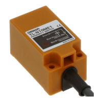
TL-N10@ TL-N20@
10
8
6
4
2
0 10 20 30 40 50 60 70 80
X
d ×
d
t
= 1 mm
Distance X (mm)
Side length of sensing object: d (mm)
Stainless steel
(SUS304)
Aluminum
Iron
Brass
22
20
18
16
14
12
10
8
6
4
2
0 10 20 30 40 50 60 70 80
X
d ×
d
t
= 1 mm
Distance X (mm)
Side length of sensing object: d (mm
Stainless steel
(SUS304)
Aluminum
Iron
Brass
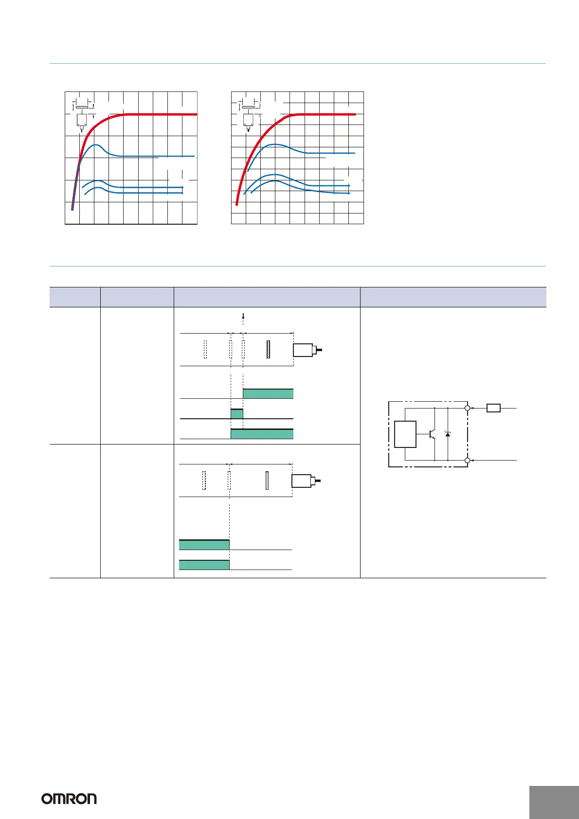
Operation
mode
Model Timing chart Output circuit
NO
TL-Q5MD1
TL-N7MD1
TL-N12MD1
TL-N20MD1
NC
TL-Q5MD2
TL-N7MD2
TL-N12MD2
TL-N20MD2
080 (TYP)100(%)
Sensing
object
Rated
sensing
distance
Stable sensing
area
Non-sensing
area
Unstable
sensing
area
Set position
Proximity Sensor
ON
OFF
ON
OFF
ON
OFF
Setting indicator
(green)
Operation indicator
(red)
Control output
+V
0 V
Load
Brown
Blue
Proximity
Sensor
main
circuit
Note: The load can be connected to either
the +V or 0 V side.
0100(%)
Sensing
object
Rated
sensing
distance
Sensing
area
Non-sensing
area
Proximity Sensor
ON
OFF
ON
OFF
Operation indicator
(red)
Control output
http://www.ia.omron.com/
7
(c)Copyright OMRON Corporation 2007 All Rights Reserved.
 Loading...


