TL-N/TL-Q/TL-G
Accessories (Order Separately)
Mounting Brackets
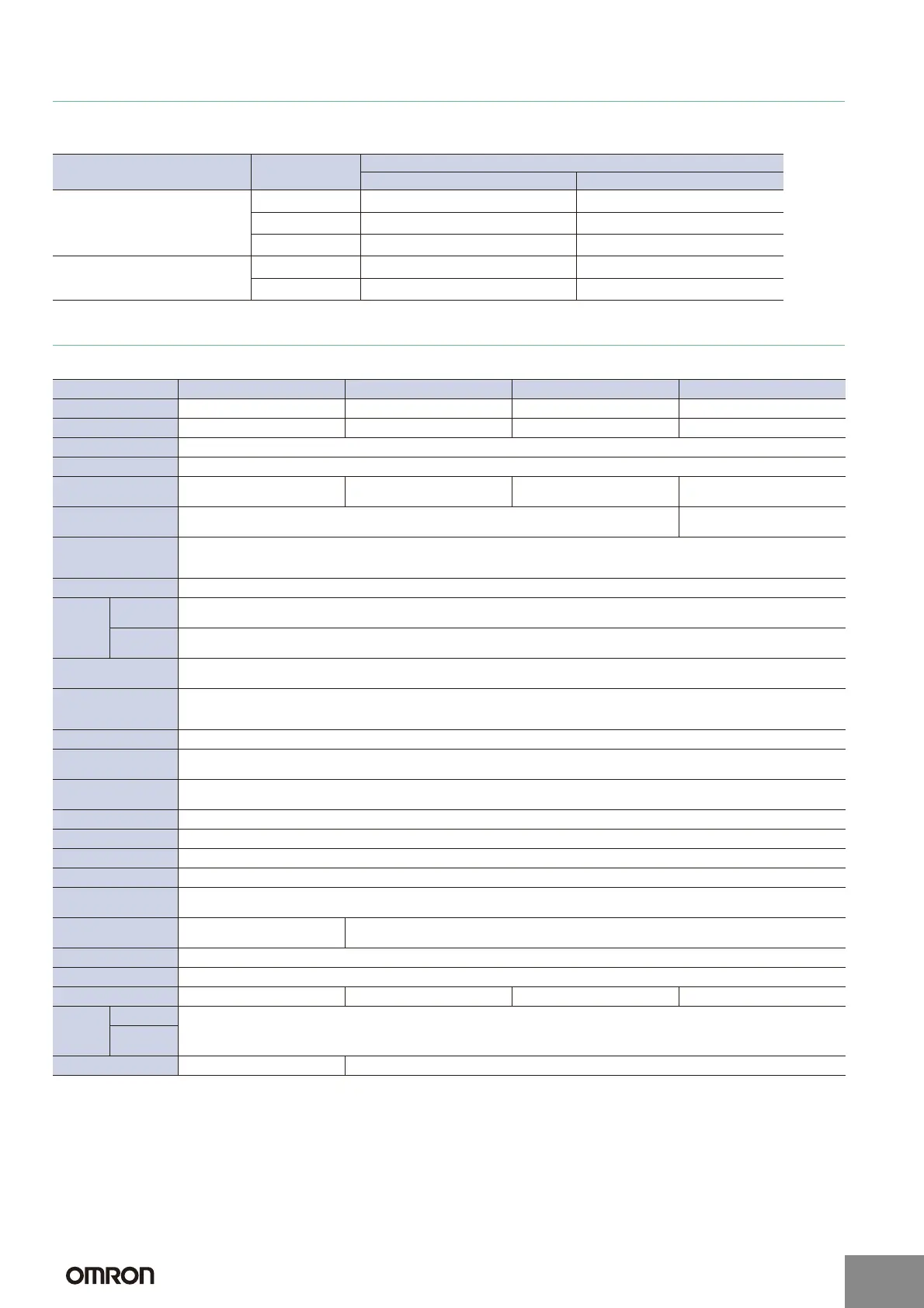
Ratings and Specifications
DC 2-Wire Models
* The response frequency is an average value.
Measurement conditions are as follows: standard sensing object, a distance of twice the standard sensing object, and a set distance of half the sensing distance.
Type Model
Applicable Sensors
Provided with these Sensors Order separately
Mounting Brackets
Y92E-C5 TL-N5ME@, TL-N7MD@ TL-N5MY@
Y92E-C10 TL-N10ME@, TL-N12MD@ TL-N10MY@
Y92E-C20 TL-N20ME@, TL-N20MD@ TL-N20MY@
Mounting Brackets for Conduits
Y92E-N5C15 --- TL-N5ME@, TL-N5MY@
Y92E-N10C15 --- TL-N10ME@, TL-N10MY@
Item Model TL-Q5MD@ TL-N7MD@ TL-N12MD@ TL-N20MD@
Sensing distance 5 mm 10% 7 mm 10% 12 mm 10% 20 mm 10%
Set distance 0 to 4 mm 0 to 5.6 mm 0 to 9.6 mm 0 to 16 mm
Differential travel 10% max. of sensing distance
Detectable object Ferrous metal (The sensing distance decreases with non-ferrous metal. Refer to Engineering Data on page 5.)
Standard sensing
object
Iron, 18 18 1 mm Iron, 30 30 1 mm Iron, 40 40 1 mm Iron, 50 50 1 mm
Response
frequency *
500 Hz 300 Hz
Power supply voltage
(operating voltage
range)
12 to 24 VDC (10 to 30 VDC), ripple (p-p): 10% max.
Leakage current 0.8 mA max.
Control
output
Load
current
3 to 100 mA
Residual
voltage
3.3 V max. (Load current: 100 mA, Cable length: 2 m)
Indicators
D1 Models: Operation indicator (red), Setting indicator (green)
D2 Models: Operation indicator (red)
Operation mode
(with sensing object
approaching)
D1 Models: NO
D2 Models: NC
Protection circuits Load short-circuit protection, Surge suppressor
Ambient
temperature range
Operating/Storage: 25 to 70C (with no icing or condensation)
Ambient
humidity range
Operating/Storage: 35% to 95% (with no condensation)
Temperature influence 10% max. of sensing distance at 23C in the temperature range of 25 to 70C
Voltage influence 2.5% max. of sensing distance at rated voltage in the rated voltage 15% range
Insulation resistance 50 M: min. (at 500 VDC) between current-carrying parts and case
Dielectric strength 1,000 VAC for 1 min between current-carrying parts and case
Vibration
resistance
Destruction: 10 to 55 Hz, 1.5-mm double amplitude for 2 hours each in X, Y, and Z directions
Shock resistance
Destruction: 500 m/s
2
3 times
each in X, Y, and Z directions
Destruction: 1,000 m/s
2
10 times each in X, Y, and Z directions
Degree of protection IEC 60529 IP67, in-house standards: oil-resistant
Connection method Pre-wired Models (Standard cable length: 2 m)
Weight (packed state) Approx. 45 g Approx. 145 g Approx. 170 g Approx. 240 g
Materials
Case
Heat-resistant ABS
Sensing
surface
Accessories Instruction manual Mounting Bracket, Instruction manual
Refer to the timing charts under I/O Circuit Diagrams on page 7 for details.
http://www.ia.omron.com/
2
(c)Copyright OMRON Corporation 2007 All Rights Reserved.
 Loading...


