Regular Payload Series-Hardware Installation Manual TM5 Series Hardware Version: 3.2 15
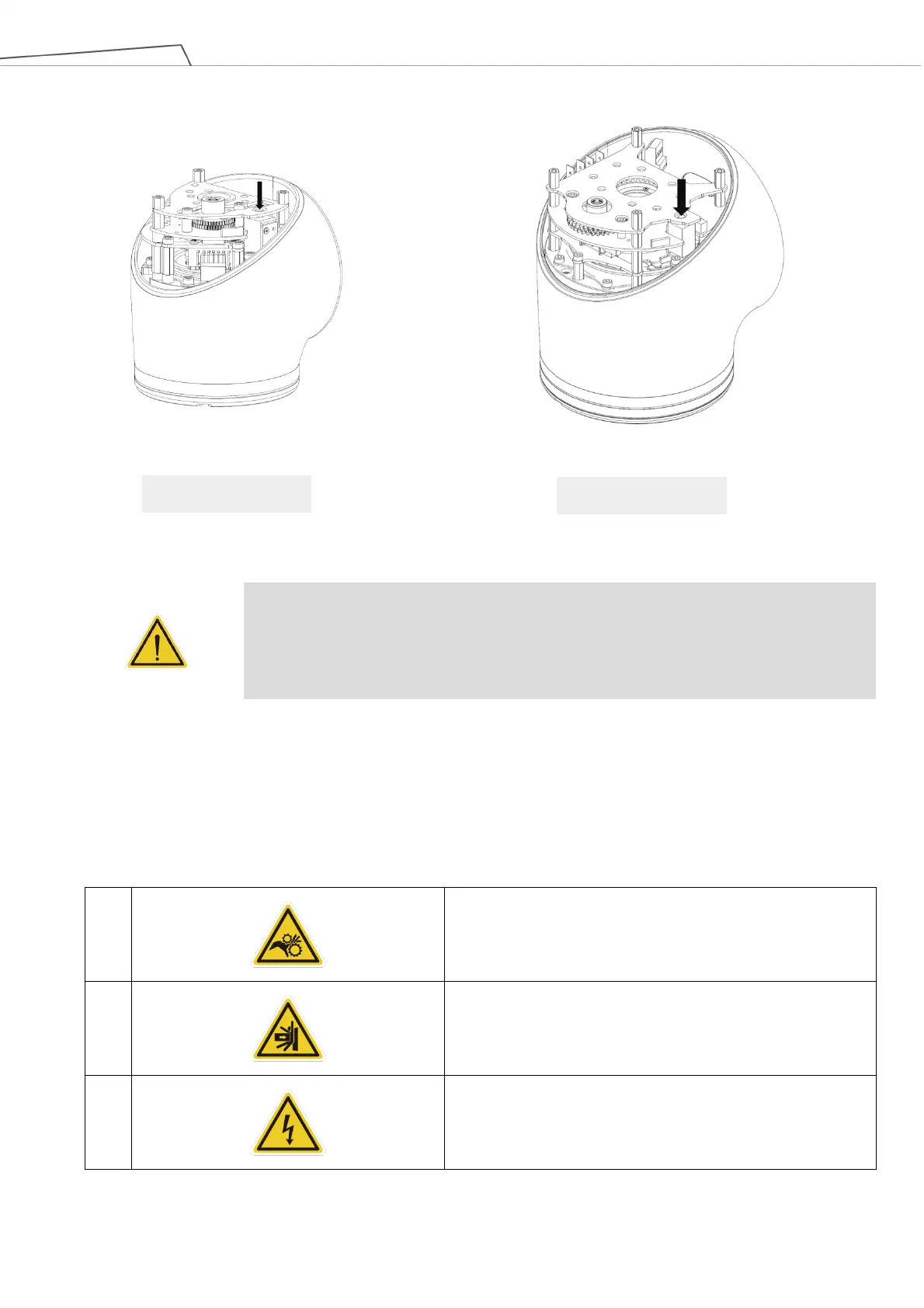
Figure 2: Reference of Brake Solenoid by Joints
WARNING:
1. Due to gravity, additional supports are recommended when manually releasing the
brake.
2. When manually moving each robot joint, the movement angle must be within a range
。
2.10 Labels
The following labels, especially the warning ones, are attached to the locations where specific dangers may occur.
Be sure to comply with description and warnings of the labels when operating to avoid accidents. Do not tear,
damage, or remove the labels. Be very careful if you need to handle the parts where the labels are attached.
A
Do not put your hand or fingers close to moving parts
B
Be careful not to be close to the moving parts and nearby
areas to avoid impact
C
Do not touch any internal electri
c parts to avoid electric
shock
st
nd
rd
th
th
th

 Loading...


