Regular Payload Series-Hardware Installation Manual TM5 Series Hardware Version: 3.2 73
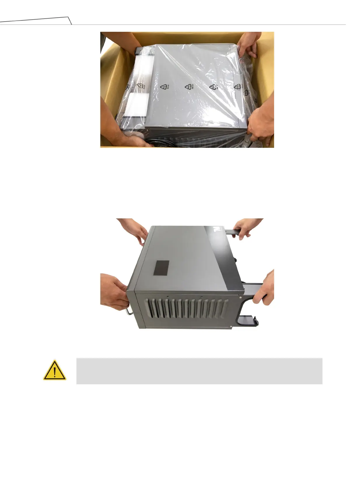
Figure 68: Moving the Control Box (1/2)
The control box should be carried by at least two people. One should hold on to the control box handles,
while the other should carry the foot stands. Before handling, the cable of the robot stick should not be
pulled to avoid any performance degradation.
Figure 69: Moving the Control Box (2/2)
WARNING:
At this stage, do not connect the power cable of the control box to any electrical outlet, or it
may cause equipment damage.
6.4.2 Verification Before Removal of the Robot Arm
The TM Robot arm cannot stand independently after being removed from the carton. Prepare four screws
(M10 *4) that used to attach the robot to the base near the robot base in advance. If the base is designed
with corresponding pinholes, mount them to the base.
 Loading...


