EN-17
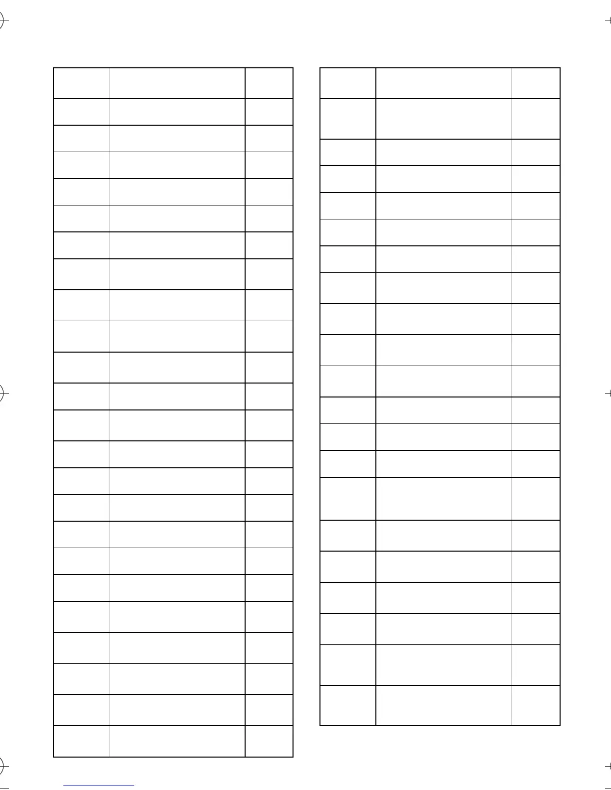
n129 PID Feedback Gain 1.00
n130 Proportional Gain (P) 1.0
n131 Integral Time (I) 1.0s
n132 Derivative Time (D) 0.00
n133 PID Offset Adjustment 0%
n134 Upper Limit of Integral Values 100%
n135 Primary Delay Time Constant
for PID Output
0.0s
n136 Selection of PID Feedback
Loss Detection
0
n137 PID Feedback Loss Detection
Level
0%
n138 PID Feedback Loss Detection
Time
1.0s
n139 Auto-tuning Selection 0
n140 Max. Output Frequency
(2nd Motor)
50.0Hz
n141 PTC Thermistor Selection 0
n142 Motor Temperature Filter Timer 0.2 s
n143 Read sequence input twice 0
n144 Stop Distance Enlarge Gain 1.00
n145 Bi-direction Selection 0
n146 Frequency Offset Selection 0
n147 Max. Voltage Output Frequency
(2nd Motor)
50.0Hz
n148 Parameter memorization at UV
detection
0
n149 Pulse Train Input Scaling 2500
(25kHz)
n150 Pulse Monitor Output
Frequency Selection
0
n151 MEMOBUS Timeover
Detection
0
Parameter
No.
Description Factory
Setting
n152 MEMOBUS Frequency
Reference and Frequency Mon-
itor unit
0
n153 MEMOBUS Slave Address 0
n154 MEMOBUS BPS Selection 2
n155 MEMOBUS Parity Selection 0
n156 Transmission Waiting Time 10ms
n157 RTS Control 0
n158 Max. Voltage (2nd Motor) 200 V
(Note 2)
n159 Mid. Output Frequency (2nd
Motor)
12.0V
(Note 2,3)
n160 Min. Output Frequency (2nd
Motor)
12.0V
(Note 2,3)
n161 Motor Rated Current (2nd Mo-
tor)
(Note 2,3)
n162 Motor Rated Slip (2nd Motor) (Note 2,3)
n163 PID Output Gain 1.0
n164 PID Feedback Value Selection 0
n165 Externally-mounting type
braking resistor overheat
protection selection
*8
0
n166 Input Open-phase Detection
Level
0%
n167 Input Open-phase Detection
Time
0s
n168 Output Open-phase Detection
Level
0%
n169 Output Open-phase Detection
Time
0.0s
n170 ENTER Command Operation
Selection (MEMOBUS Commu-
nication)
0
n171 Frequency reference bias
upper limit (UP/DOWN
command 2)
0.0%
Parameter
No.
Description Factory
Setting
I43-EN-01+V7+Quick_Guide.book Seite 17 Dienstag, 25. April 2006 8:56 08
 Loading...


