23
ZX SERIESZX SERIES
Installation
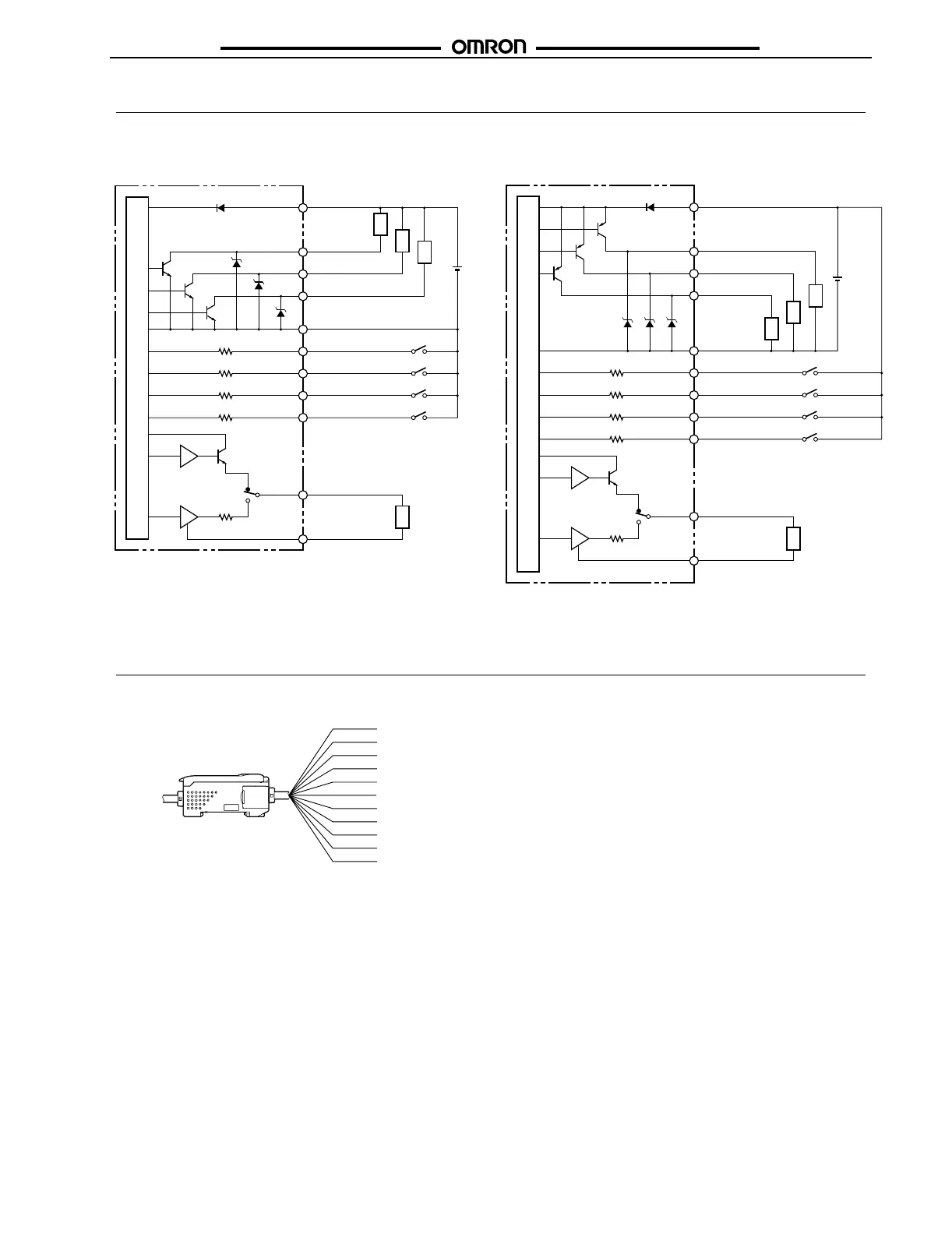
■ I/O Circuit Diagrams
Connections
■ Amplifier Unit
NPN Amplifier Unit: ZX-LDA11
Internal circuits
Brown: 12 to 24 VDC
Load
White: HIGH
output
Green: PASS output
Gray: LOW output
Blue: GND (0V)
Pink: Laser OFF input
Purple: Timing input
Orange: Zero reset input
Red: Reset input
Black: Linear output
Shield: Linear GND
Current output: 300 Ω max.
Voltage output: 10 kΩ min.
Current output
4 to 20 mA
Current/voltage
switch
Voltage output
±4V
12 to
24 VDC
Load
Load
Load
PNP Amplifier Unit: ZX-LDA41
Internal circuits
Brown: 12 to 24 VDC
Load
White: HIGH output
Green: PASS output
Gray: LOW output
Blue: GND (0V)
Pink: Laser OFF input
Purple: Timing input
Orange: Zero reset input
Red: Reset input
Black: Linear output
Shield: Linear GND
Current output: 300 Ω max.
Voltage output: 10 kΩ min.
Current output
4 to 20 mA
Current/voltage
switch
Voltage output
±4V
Load
Load
Load
12 to
24 VDC
100 Ω
100 Ω
Brown:
White:
Green:
Gray:
Blue:
Pink:
Purple:
Orange:
Red:
Black:
Shield:
Note: 1. Use a separate stabilized power supply for the Amplifier Unit,
particularly when high resolution is required.
2. Wire the Unit correctly. Incorrect wiring may result in damage
to the Unit. (Do not allow wiring, particularly the linear output,
to come into contact with other lines.)
3. Use the 0-V line (blue) for the power supply and use the
shield wire (linear output ground) together with the linear out-
put (black line) for linear output. Each of these grounds must
be used for the designed purpose. When not using the linear
output, connect the linear ground (shield) to the 0-V ground.
12 to 24 VDC
HIGH output
PASS output
LOW output
GND (0V)
Laser OFF input
Timing input
Zero reset input
Reset input
Linear output
Linear output GND

 Loading...


