12
ZX SERIESZX SERIES
■ Timing Functions
Setting Time delay
The time set for the timer is the delay time for the ON-delay timer,
the delay time for the OFF-delay timer, or the pulse width for the
one-shot timer. Set the time according to the requirements of the
control system (e.g., PLC). The timer time can be set to between
0 and 5,999 ms.
Timer Disable
If the timer is disabled, judgement outputs will be made immedi-
ately and the output response time will be determined by the
number of samples to average.
OFF-delay Timer
When the measured value changes from HIGH to PASS or from
LOW to PASS, turning OFF the PASS output is delayed for the
timer time.
ON-delay Timer
When the measured value changes from HIGH to PASS or from
LOW to PASS, turning ON the PASS output is delayed for the
timer time.
One-shot Timer
When the measured value changes from HIGH to PASS or from
LOW to PASS, the PASS output is turn ON with a pulse width
equivalent to the timer time.
When PASS output pulses overlap, the latter pulse has priority.
Therefore, overlapping pulses might sometimes become a single
pulse rather than separate pulses.
Note: Neither the HIGH nor the LOW output are output when the
one-shot timer
■
Two-sensor operation
Two-sensor operation enables mutual operation using the mea-
sured values from the two Sensor Heads to generate final out-
puts. Two kinds of outputs, A−B or A+B, can then be selected.
Note: The ranges of display values and linear output values are
automatically doubled when two-sensor operation is used.
An example application of Sensor Heads is given in the
following table when the sensing distance is 100
± 40 mm
.
Note: Correct distance operation cannot be performed if Sensor
Heads with different sensing distances are used.
•A − B
The difference between the measured values of the two Sensor
Heads is the final output. The measured value of the 1CH Ampli-
fier Unit is B and the measured value of the 2CH Amplifier Unit is
A.
•A + B
The sum of measured values of the two Sensor Heads is the final
output. The measured value of the 1CH Amplifier Unit is B and
the measured value of the 2CH Amplifier Unit is A.
• Operation Result Output
The result of the operation is displayed on and output from the
2CH Amplifier Unit. The B measured value is displayed on and
output from the 1CH Amplifier Unit.
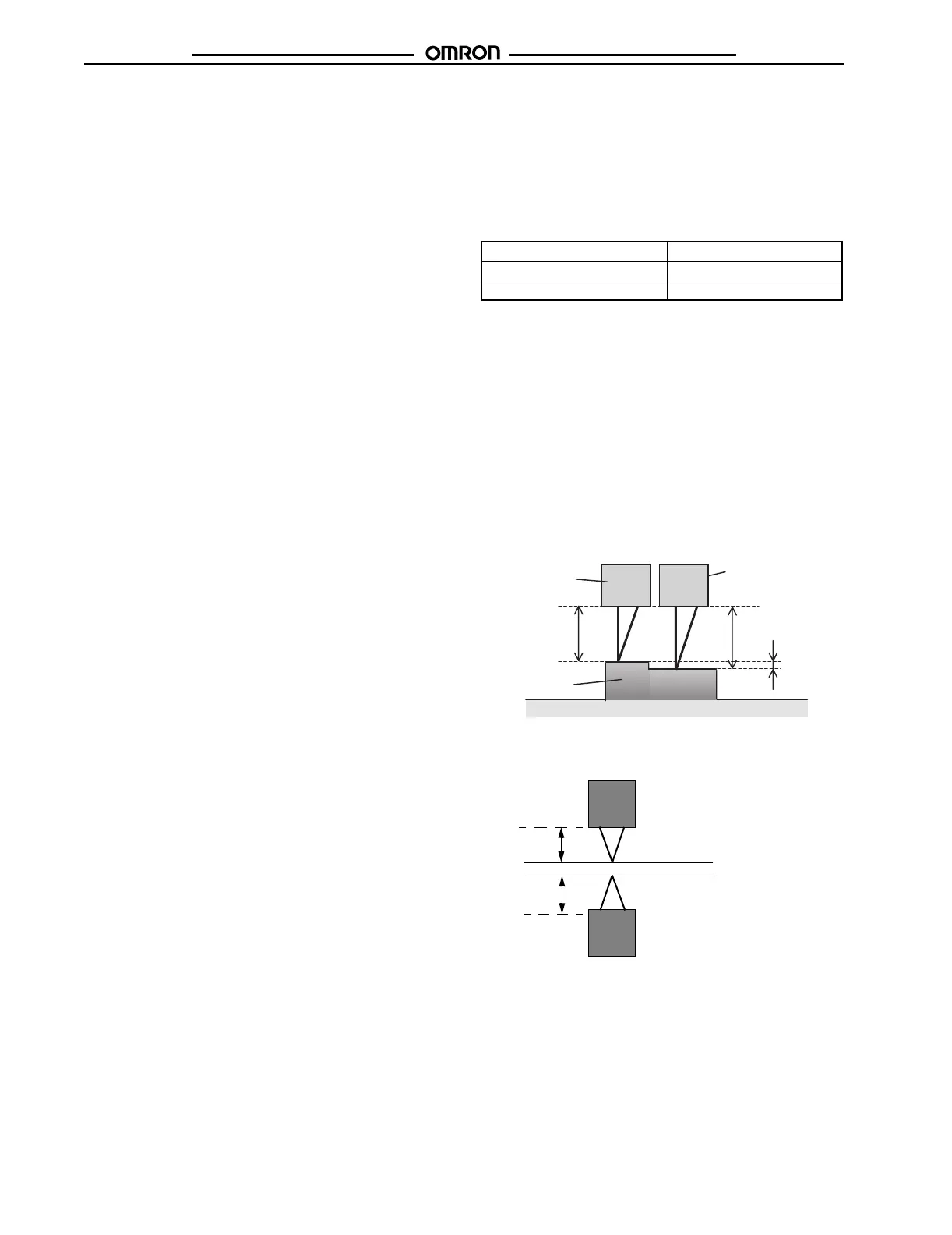
• Two sided thickness measurement
Linear output 4 to 20 mA
A − B −80 to 80
A + B 120 to 280
Sensor Head
Sensor Head
1CH
2CH
BA
A − B
Sensing object
B
A
Sensor Head
1 CH
Sensor Head
2 CH

 Loading...


