ZX2
Safety Precautions
For details, refer to common precautions, warranty, limitation of liability, and other related information.
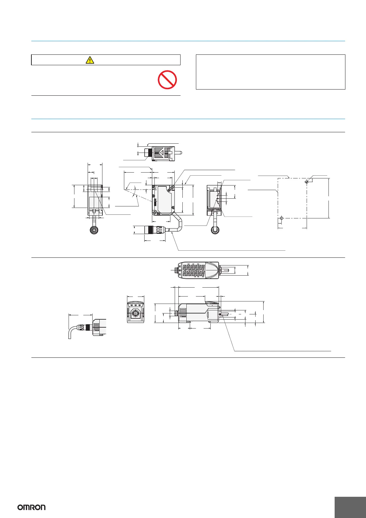
Dimensions
Units
This product is not designed or rated for ensuring
safety of persons.
Do not use it for such purposes.
Precautions for Correct Use and Other Details
Refer to the “Smart Sensors Laser Displacement Sensors
CMOS Type ZX2 Series User’s Manual” (Cat. No. Z310).
(Unit: mm)
Tolerance class IT16 applies to dimensions in thes data sheet unless otherwise specified.
Reference surface
Reference surface
Range indicator
Laser
warning light
Range indicator
Reference surface
4
Two, 3.2-dia. (Mounting holes)
Emitter
axis
Receiver axis
Emitter axis
6
Vinyl insulated round robot cable, 4.7 dia., 4 conductors
(Conductor cross-section: 0.086 mm
2
/Insulator diameter: 0.9 mm)
Standard length: 0.5 m, Minimum bending radius: 30 mm
9.7
Emitter center
15.1
10.1
4±0.05
Two, M 3
Mounting
reference surface
Mounting
reference surface
4±0.05
43.5±0.05
4.8
4.8
10.5
7
35.3
16.7
(9.7)
L *
27.5
35.535.5
7
A*
4
20.9
39.5
47.547.5
28.43
29.8
12.6 dia.
31.5±0.05
22.622.6
Sensor Heads
ZX2-LD50
ZX2-LD50L
ZX2-LD100
ZX2-LD100L
ZX2-LD50V
* In the case of ZX2-LD50 (L), L=50, A=21 °
In the case of ZX2-LD100 (L), L=100, A=11.5 °
Mounting Dimensions
Note: Attach the enclosed
ferrite core (16.5 dia.,
length: 30 mm) to the
cable within 100 mm
from the Sensor Head.
6.2
4.2
6.1
9.6
Vinyl insulated round cable,5.2 dia., 11 conductors
(Conductor cross-section 0.09 mm
2
/Insulator diameter: 0.7 mm)
Standard length: 2 m, Minimum bending radius: 30 mm
The analog output line (black) has double shielding and
the diameter of the insulator is 2.3 mm.
11.7
50
15.4
16.6
38.4
*1
10.9
16.9
47.6
72
(when cover open, 84.6)
34.2
20.7
36.8
30
18
*2
Note:
Amplifier Units
ZX2-LDA11
ZX2-LDA41
*1. Maximum height when cover open: 56
*2. Minimum length when connected: 50