ZX2
10
Beam Size
Spot Beams
ZX2-LD50
ZX2-LD100
Line Beams
ZX2-LD50L
ZX2-LD100L
* Measurement distance displayed by the amplifier unit. The measurement distance displayed by the amplifier unit takes the measurement center
distance as 0, and the NEAR and FAR sides from the sensor are displayed by + and −, respectively.
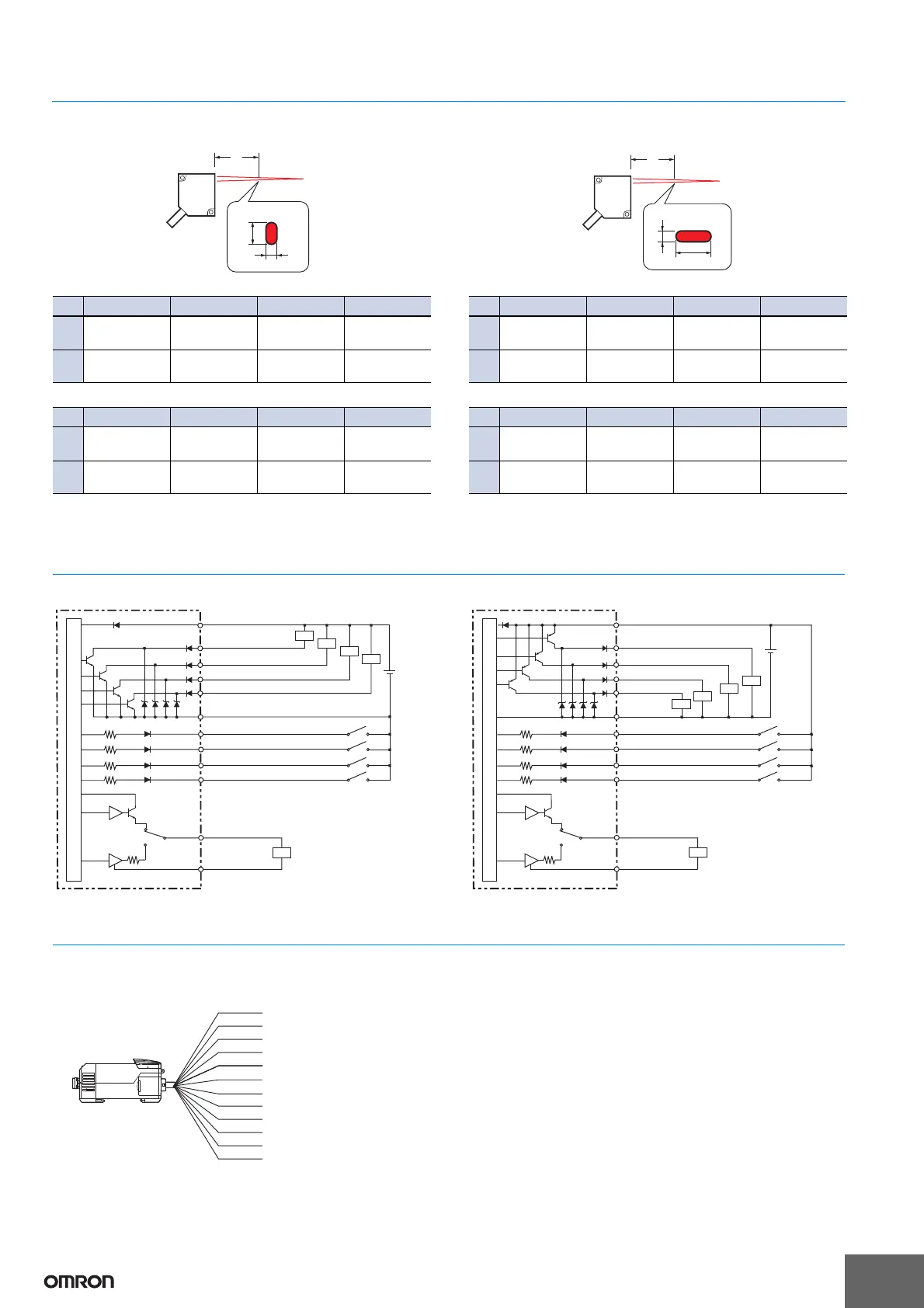
I/O Circuit Diagrams
NPN Amplifier Unit (ZX2-LDA11) PNP Amplifier Unit (ZX2-LDA41)
Wiring
Amplifier Units
ZX2-LDA11/ZX2-LDA41
L * +10 mm 0 mm −4 mm −10 mm
X
Approx.
600 μm
Approx.
160 μm
Approx.
40 μm
Approx.
220 μm
Y
Approx.
350 μm
Approx.
90 μm
Approx.
60 μm
Approx.
130 μm
L * +35 mm 0 mm −20 mm −35 mm
X
Approx.
1.1 mm
Approx.
400 μm
Approx.
70 μm
Approx.
250 μm
Y
Approx.
550 μm
Approx.
190 μm
Approx.
110 μm
Approx.
150 μm
Beam cross-section
Y
X
L
L * +10 mm 0 mm −4 mm −10 mm
X
Approx.
2.6 mm
Approx.
2.6 mm
Approx.
2.6 mm
Approx.
2.6 mm
Y
Approx.
350 μm
Approx.
90 μm
Approx.
60 μm
Approx.
130 μm
L * +35 mm 0 mm −20 mm −35 mm
X
Approx.
2.1 mm
Approx.
2.5 mm
Approx.
2.7 mm
Approx.
2.9 mm
Y
Approx.
550 μm
Approx.
190 μm
Approx.
110 μm
Approx.
150 μm
Beam cross-section
Y
X
L
100 Ω
Brown: 10 to 30 VDC
10 to
30 VDC
White: HIGH judgement output
Load
Load
Load
Load
Load
Green: PASS judgement output
Gray: LOW judgement output
Yellow: Error output
Blue: GND (0 V)
Pink: LD-OFF input
Purple: Timing input/BANK input 0
Orange: Zero reset input
Red: Reset input/BANK input 1
Current output
4 to 20 mA
Current output: 300 Ω or lower
Voltage output: 10 kΩ or higher
Voltage output
±5 V
1 to 5 V
Current/voltage
output switch
Black: Analog output
Shield: Analog GND
Internal circuits
100 Ω
Brown: 10 to 30 VDC
White: HIGH judgement output
Load
Load
Load
Load
Load
Green: PASS judgement output
Gray: LOW judgement output
Ye l l o w: Error output
Blue: GND (0 V)
Pink: LD-OFF input
Purple: Timing input/BANK input 0
Orange: Zero reset input
Red: Reset input/BANK input 1
Current output
4 to 20 mA
Internal circuits
Current output: 300 Ω or lower
Voltage output: 10 kΩ or higher
Voltage output
±5 V
1 to 5 V
Current/voltage
output switch
Black: Analog output
Shield: Analog GND
10 to
30 VDC
10 to 30 VDC
GND (0V)
HIGH judgement output
PASS judgement output
LOW judgement output
Analog output
Error output
Analog GND
LD-OFF input
Zero reset input
Timing input/BANK input 0
Reset input/BANK input 1
Black
Ye l l o w
Shield
Pink
Orange
Purple
Red
Gray
Green
White
Blue
Brown
Note: 1. Use a separate stabilized power supply for the Amplifier Unit,
particularly when high resolution is required.
2. Wire the Unit correctly. Incorrect wiring may result in damage to the
Unit. (Do not allow wiring, particularly the Analog output, to come
into contact with other wires.)
3. Use the 0-V ground (blue) for the power supply and use the Analog
ground (shield) for Analog output. Each of these grounds must be
used for the designed purpose. When not using the Analog output,
connect the Analog ground (shield) to the 0-V ground (blue).