Material: Stainless steel
(SUS304)
Thickness: 2.0 mm
Material: Stainless steel (SUS304)
Thickness: 3.0 mm
Accessories: Phillips screws (M3×30): 2
Nut plate: 1
Nut plateMounting Bracket
R48.1
3.2 dia.
5
5
31.4
(36.4)
58
23
3.5
2-R3
54.1
48.1
2
-
M3
P=0.5
24.5°
(Regular-reflective
Sensor mounting)
34.7°
(Diffuse-reflective
Sensor mounting)
6
2-R3
14
3.2
3.2
5.2
12
8.8
16.8
16.8
16.8
(26.4)
9.6
*
Nut plate
Use this Mounting Bracket when installing the ZX2-LD100 (L) as a normal
Diffuse-reflective or Regular-reflective Sensor Head.
Material: Stainless steel
(SUS304)
Thickness: 2.0 mm
Material: Stainless steel (SUS304)
Thickness: 3.0 mm
Accessories: Phillips screws (M3×30): 2
Nut plate: 1
Mounting Bracket
3.5
54.1
48.1
2-M3
P=0.5
R48.1
5
5
31.6
(36.6)
56
23
2-R3
3.2 dia.
29.2°(Regular-reflective
Sensor mounting)
34.7°(Diffuse-reflective
Sensor mounting)
6
2-R3
14
3.2
12
8.8
3.2
5.2
16.8
16.8
16.8
(26.4)
9.6
Mounting Bracket
Nut plate
Phillips screws
22.6
10.5°
*
2
*
1
(32)
Installation Method for Regular-reflective Sensor Head
Using a E39-L178 Mounting Bracket:
Note:
When securing the Sensor Head in the
Mounting Bracket, insert the screws into
the side of the Sensor Head where the
warning label is located and secure the
Sensor Head into place.
*1. The measurement distance reference
position is the end of the Mounting Bracket.
*2. For the Regulalr-reflective Sensor Heads,
rotate the Sensor Head counterclockwise,
secure it in place, and then perform any
necessary fine adjustments.
Mounting Bracket
Nut plate
Phillips screws
(32)
22.6
*
2
*
1
5.75°
Installation Method for Regular-reflective Sensor
Heads (Installing a Diffuse-reflective Sensor
Head as a Regular-reflective Sensor Head)
Using a E39-L179 Mounting Bracket:
Note:
When securing the Sensor Head in the
Mounting Bracket, insert the screws into the
side of the Sensor Head where the warning
label is located and secure the Sensor Head
into place.
*1. The measurement distance reference position is
the end of the Mounting Bracket.
*2. For the IInstalling a Diffuse-reflective Sensor as
a Regular-reflective Sensor, rotate the Sensor
Head counterclockwise, secure it in place, and
then perform any necessary fine adjustments.
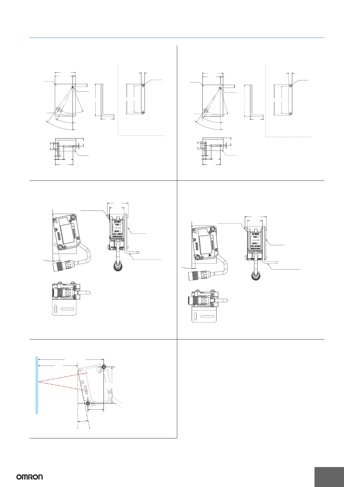
workpiece
Measurement
center distance
10.5°
*
The mounting hole dimensions in parentheses
(reference values) are for when the Sensor is
installed at 10.5°.
Adjust the installation so that the angle is 10.5° ±0.1°.
Not Using a Mounting Bracket:
Tilt the Sensor Head towards the workpiece as shown below.