ZX2
12
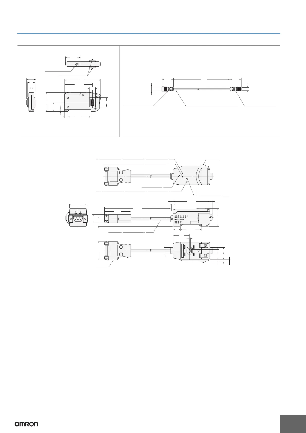
Accessories (sold separately)
15.115.1
Coupled indicators
Coupling connectors
8
3.4
12
14.4
3030
9.5
24.9
44.05
5757
5
36.7
15
Amplifier Unit
attachment connector
(female, 6 poles)
Sensor Head
attachment connector
(male, 6 poles)
Vinyl insulated round robot cable, 4.7 dia.
(ZX2-XC20R: 5.1 dia.)
12 dia.
29.8
28.9
L *
12.6 dia.
Sensor Head Extension Cables
ZX2-XC1R
ZX2-XC4R
ZX2-XC9R
ZX2-XC20R
* Length L is as follows.
ZX2-XC
1R: 1 m, ZX2-XC4R: 4 m, ZX2-XC9R: 9 m, ZX2-XC20R: 20 m
Minimum bending radius: 30 mm
Note: Attach the enclosed ferrite cores (16.5 dia., length: 30 mm) within 100 mm of
each end of the extension cable.
Coupling
connector
Connector
Sensor communications indicator (communications operation)
External terminal
communications indicator
(communications operation)
Sensor communications indicator (communications error)
External terminal communications indicator (communications error)
Power supply indicator
30
15
13.2
(336)
64.3
31.5
36.8
29
11.7
4.3
3 5 6.55
11.7
2.2
13
4.2 4.2
3
(46)
(33.1)
Vinyl -insulated round cable,
5.23 dia. Standard length 100 mm
ZX2-series Communications Interface Unit
ZX2-SF11