-----------------------
blow to wedge the new valve seat securely in
place. The valve seat must be staked to en-
sure
a tight fit and eliminate the danger of its
loosening in the bore. Before installing the
valves, refinish the valve seat inserts.
Valve Tappets
The engine is equipped with adjustable valve tap-
pets. Adjust the valve clearance only when the en-
gine is at ambient temperature.
Tappet Adjustment Procedure
1 . Remove all parts that block access to the valve
tappets.
2. Remove the spark plugs, to make turning the
engine easier.
3. Place a socket wrench on the flywheel
capscrew, and rotate the crankshaft in
a clock-
wise direction until the left intake valve (viewed
from flywheel end) opens and closes. Con-
tinue turning the crankshaft until the TDC mark
on the flywheel is lined up with the TDC mark
on the gear cover. This should place the left
piston (#1) at the top of its compression stroke.
Verify that the left intake and exhaust valves
are closed and that there is no pressure on the
valve lifters.
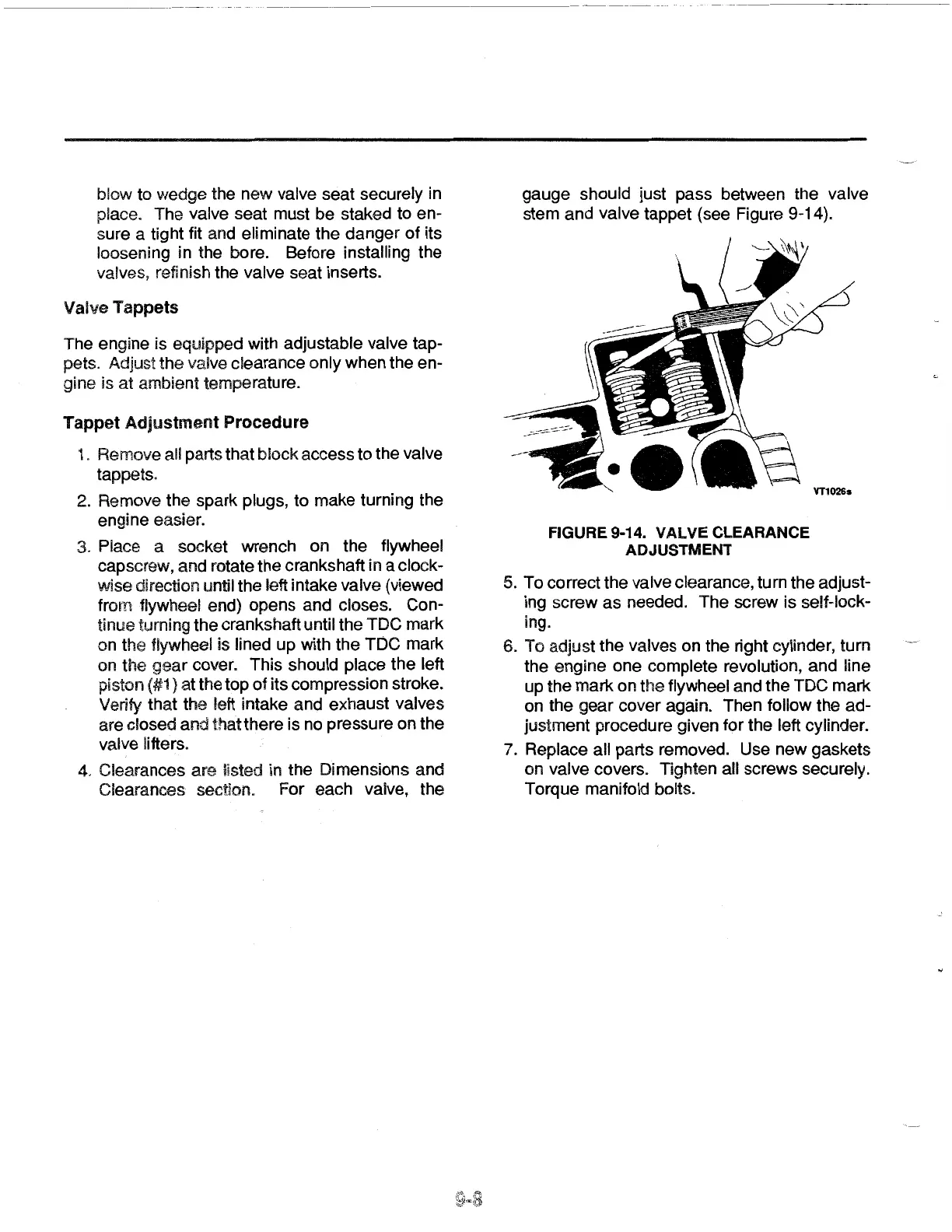
4.
Clearances are listed in the Dimensions and
Clearances section. For each valve, the
gauge should just pass between the valve
stem and valve tappet (see Figure 9-14).
FIGURE 9-14. VALVE CLEARANCE
ADJUSTMENT
5. To correct the valve clearance, turn the adjust-
ing screw as needed. The screw is self-lock-
ing.
6. To adjust the valves on the right cylinder, turn
the engine one complete revolution, and line
up the mark on the flywheel and the TDC mark
on the gear cover again. Then follow the ad-
justment procedure given for the left cylinder.
7.
Replace all parts removed. Use new gaskets
on valve covers. Tighten all screws securely.
Torque manifold bolts.
 Loading...