PISTON ASSEMBLY
The piston assembly consists of:
• Piston
• Piston rings
• Piston pin
• Connecting rod assembly and bearing
After removal from the engine, all parts must be
carefully inspected for damage and wear before
they are replaced.
Piston
Removal
and
Disassembly
Procedure
1. Remove carbon from the top
of
cylinder bore,
and check for a ridge. Remove this ridge (see
Figure
9-20) with a ridge reamer before at-
tempting piston removal.
lA CAUTION I
Improper
use
of
a ridge reamer
can damage the
cylinder
bore. Use this
tool
with extreme care.
CT105&
FIGURE 9-20. REMOVING WEAR RIDGE
2. Turn the crankshaft until a piston is
at
the bot-
tom
of
its stroke. Remove
the
nuts from the
connecting rod bolts.
3. Lift the rod bearing cap from the rod, and push
the rod and piston assembly
out
the top
of
the
cylinder with the handle end
of
a hammer. Be
9-13
careful not to scratch the crankpin
or
the cylin-
der
wall when removing these parts.
4. Mark each piston and rod assembly so they
can
be
returned to their respective cylinders af-
ter overhaul. Keep
the
connecting rod bearing
caps with their respective rods.
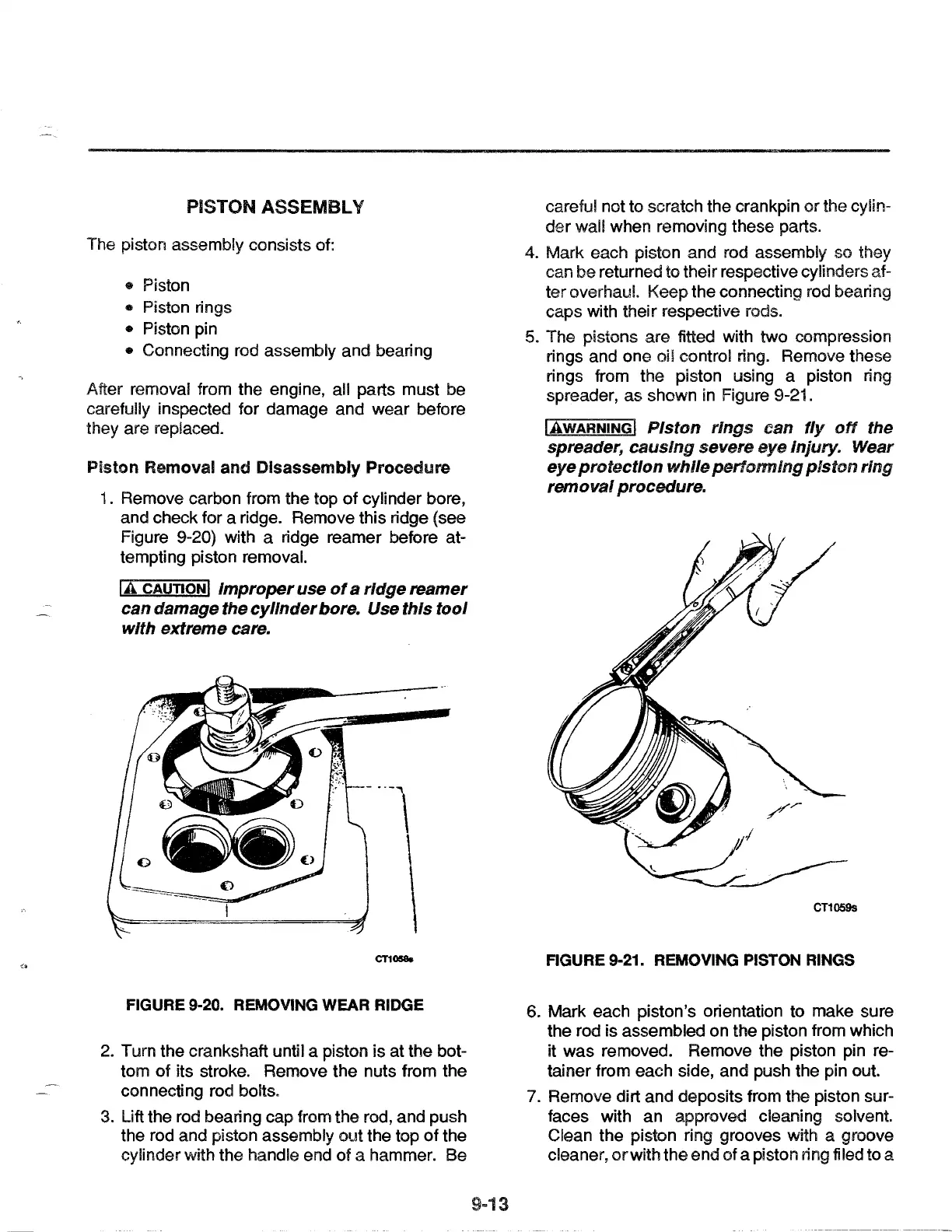
5. The pistons are fitted with
two
compression
rings and
one
oil control ring. Remove these
rings from the piston using a piston ring
spreader,
as
shown in Figure 9-21.
IAwARNINGI
Piston rings can
fly
off
the
spreader, causing severe eye injury. Wear
eye
protection
while
performing
piston
ring
removal procedure.
CT1059s
FIGURE 9-21. REMOVING PISTON RINGS
6.
Mark
each piston's orientation to make sure
the rod is assembled
on
the piston from which
it
was
removed. Remove the piston pin re-
tainer from each side, and push the pin out.
7. Remove dirt
and
deposits from the piston sur-
faces with
an
approved cleaning solvent.
Clean the piston ring grooves with a groove
cleaner,
or
with
the
end
of
a piston ring filed to a
 Loading...