GENERATOR TESTING
This section describes test procedures for check-
ing field voltage, rotor, and stator.
Field Voltage Test
To check the field voltage, remove the brush block
cover and connect a
DC
voltmeter to the brush
block terminals. Connect the positive lead to the B+
(outboard) terminal and the negative lead to the B-
(inboard) terminal.
Start the genset and allow
it
to stabilize. Measure
the field voltage with no load applied and then with
full load applied. Both readings should fall between
18 and 60 volts DC, and be stable
at
constant load.
If field voltage fluctuates at constant load, refer to
Troubleshooting in this section; a possible gover-
nor
or
voltage regulator problem exists.
Stop the genset, remove the test leads and replace
the brush block cover when the test is complete.
Rotor Test
The rotor may be tested for grounded, open,
or
shorted windings using an ohmmeter. Figures
8-11
and 8-12 show the rotor removed from the genera-
tor for testing. However,
it is possible to test the ro-
tor without removing it from the generator. To ob-
tain access to the slip rings, remove the brush block
cover. Lift the brush lead wires and insert a brush
retaining wire from outside stator housing, through
brush block assembly to hold the brushes off the
slip rings during testing.
8-15
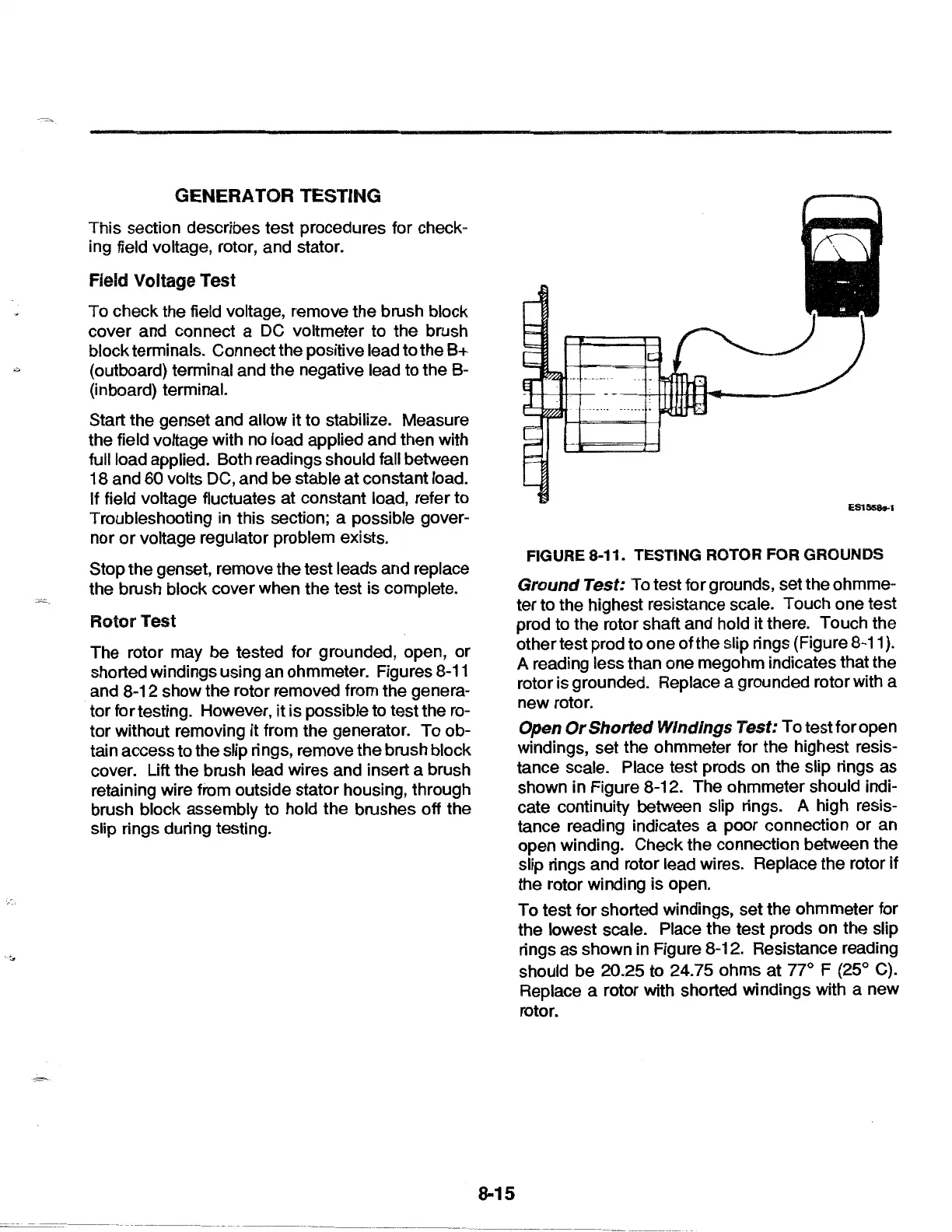
FIGURE 8-11. TESTING ROTOR FOR GROUNDS
Ground
Test: To test for grounds, set the ohmme-
ter to the highest resistance scale. Touch one test
prod to the rotor shaft and hold
it there. Touch the
other test prod to one of the slip rings {Figure
8-11
}.
A reading less than one megohm indicates that the
rotor is grounded. Replace a grounded rotor with a
new rotor.
Open
Or
Shorted Windings Test: To test for open
windings, set the ohmmeter for the highest resis-
tance scale. Place test prods
on
the slip rings as
shown in Figure 8-12. The ohmmeter should indi-
cate continuity between slip rings. A high resis-
tance reading indicates a poor connection or an
open winding. Check the connection between the
slip rings and rotor lead wires. Replace the rotor
if
the rotor winding is open.
To test for shorted windings, set the ohmmeter for
the lowest scale. Place the test prods on the slip
rings as shown in Figure 8-12. Resistance reading
should be 20.25 to 24.75 ohms
at
77° F (25° C).
Replace a rotor with shorted windings with a new
rotor.
 Loading...