GOVERNOR AND CARBURETOR
ADJUSTMENTS
The governor operates the throttle
to
maintain a
nearly constant engine speed (frequency) as the
electrical load on the genset varies. Careful adjust-
ments of the carburetor and governor are essential
for top performance. Perform all necessary engine
and generator maintenance and repairs before
making these adjustments.
Governor and carburetor adjustments should be
done together. They require the use of meters to
measure voltage, frequency and amperage and a
.stepped load bank of at least 8
kW,
where a portion
of at least 600 watts is variable. Digital meters are
recommended. Accuracy should be at least 0.3 per-
cent for frequency measurement and 0.5 percent
for voltage measurement.
Beginning
Spec
F,
carburetor fuel mixture adjust-
ing screws are not accessible. Other than turning
the altitude adjust knob to compensate for altitude
on
gasoline carburetors, fuel mixture adjustments
should not be attempted.
IAWARNINGI Unauthorized
modifications
or
re-
placement
of
fuel, exhaust,
air
intake
or
speed
control
system components
that
affect
engine
emissions are
prohibited
by
law
in
the
State
of
California.
IAWARNINGI Disconnect
or
unplug
all
voltage
and
frequency sensitive devices
such
as
TVs,
ACTUATOR
LEVER
GOVERNOR
ACTUATOR
/
GOVERNOR
ROD
VCRs,
computers
and
other
solid-state elec-
tronic
devices before making
governor
and
car-
buretor
adjustments. Typically, some internal
circuits
are
powered
when these types
of
de-
vices are
plugged
in, even
if
the device has been
switched
"OFF". These
circuits
can
be
dam-
aged
by
variations
in
voltage
and
frequency
that
occur
during
these tests.
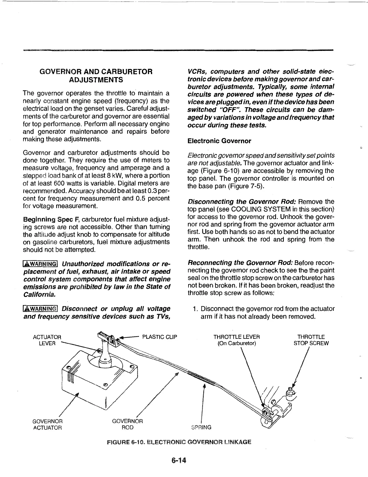
Electronic Governor
Electronic
governor
speed
and
sensitivity
set
points
are
not
adjustable. The governor actuator and link-
age (Figure
6-1
0)
are accessible by removing the
top panel. The governor controller is mounted on
the base pan (Figure 7-5).
Disconnecting
the Governor Rod: Remove the
top panel (see COOLING SYSTEM in this section)
for access to the governor rod. Unhook the gover-
nor rod and spring from the governor actuator arm
first. Use both hands so as not to bend the actuator
arm. Then unhook the rod and spring from the
throttle.
Reconnecting the Governor Rod: Before recon-
necting the governor rod check to see the the paint
seal
on
the throttle stop screw
on
the carburetor has
not been broken. If it has been broken, readjust the
throttle stop screw as follows:
1.
Disconnect the governor rod from the actuator
arm if it has not already been removed.
1
SPRING
FIGURE 6-10. ELECTRONIC GOVERNOR
UNKAGE
6-14
 Loading...