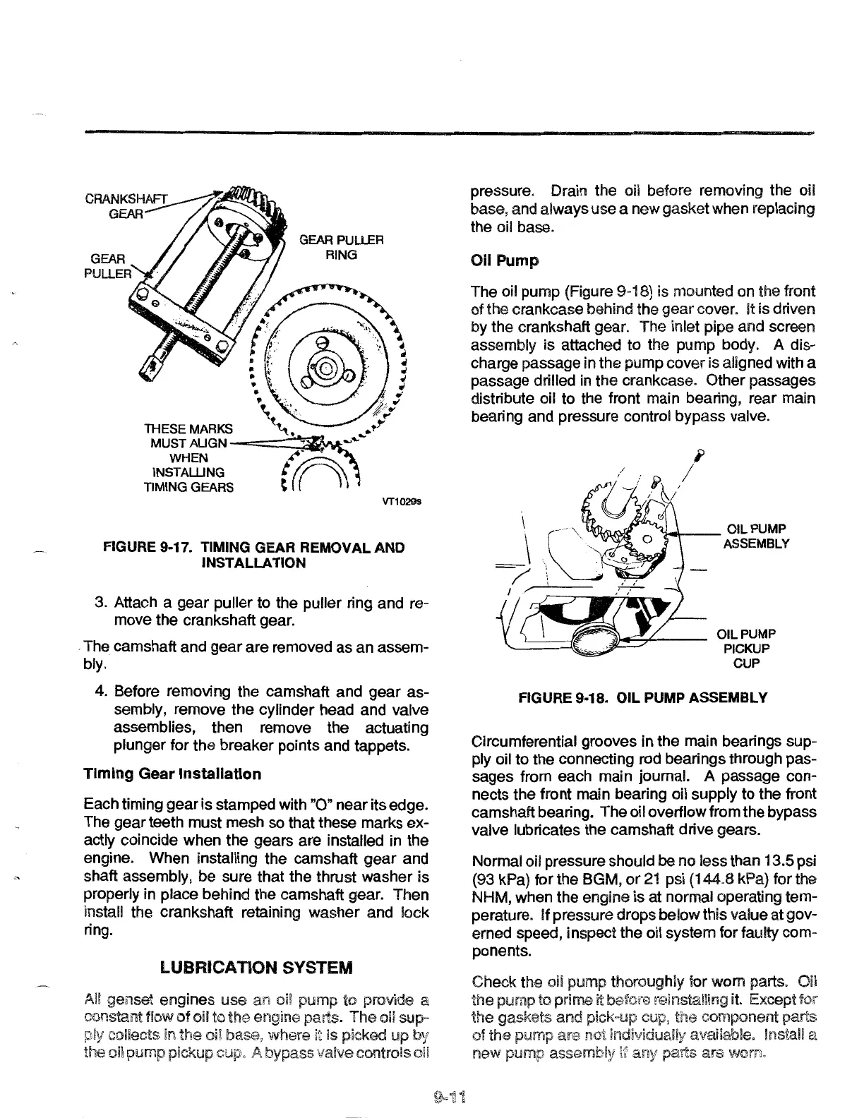
GEARPUUER
RING
VT1029s
FIGURE 9-11. TIMING GEAR REMOVAL AND
INSTALLATION
3. Attach a
gear
puller to the puller ring and re-
move the crankshaft gear.
. The camshaft and
gear
are removed
as
an assem-
bly.
4. Before removing the camshaft and
gear
as-
sembly, remove the cylinder head and valve
assemblies, then remove the actuating
plunger for the breaker points and tappets.
Timing Gear Installation
Each timing
gear
is
stamped with
"0"
near its edge.
The gear teeth must mesh so that these marks ex-
actly coincide when the gears are installed in the
engine. When installing the camshaft
gear
and
shaft assembly, be sure that the thrust washer
is
properly in place behind the camshaft gear. Then
install the crankshaft retaining
washer
and lock
ring.
LUBRICATION SYSTEM
AI! genset engines
use
an
oil pump to provide a
constant flow
of
oil to engine parts. The oil sup-
collects in the oil base,
where~~
is picked up
by
the oil pump pickup A bypass vaive controls
pressure. Drain the oil before removing the oil
base, and always use a new gasket when replacing
the oil base.
Oil Pump
The oil pump (Figure 9-18) is mounted on the front
of
the crankcase behind the
gear
cover. It is driven
by the crankshaft gear. The inlet pipe and screen
assembly is attached
to
the pump body. A dis-
charge passage in
the
pump
cover
is aligned with a
passage drilled in the crankcase. Other passages
distribute oil
to
the front main bearing, rear main
bearing and pressure control bypass valve.
OIL PUMP
PICKUP
CUP
FIGURE 9-18. OIL PUMP ASSEMBLY
Circumferential grooves in the main bearings sup-
ply oil
to
the connecting rod bearings through pas-
sages from each main journal. A passage con-
nects the front main bearing oil supply
to
the front
camshaft bearing. The oil overflow from the bypass
valve lubricates the camshaft drive gears.
Normal oil pressure should be no less than
13.5 psi
(93 kPa) for the BGM,
or
21
psi (144.8 kPa) for the
NHM, when the engine is at normal operating tem-
perature. If pressure drops below this value at gov-
erned speed, inspect the oil system for faulty com-
ponents.
Check the oil pump thoroughly for worn parts. Oil
the pump to prime it before reinstalling
it.
Except for
the gaskets and pick-up cup, component parts
of the pump are indivlduaJiy available. Install a
new pump assembly
I'~
parts are
worrt
 Loading...