Section
9.
Engine Block Assembly
GENERAL
The engine block assembly includes:
• Pistons and connecting rods
• Crankshaft
•Camshaft
• Valves and lifters
• Cylinder heads
• Lubrication system
• Timing gears
• Governor mechanism (mechanical)
•Bearings
• Cylinder block
Performing major service on the block assembly re-
quires that the genset
be
removed from the vehicle
(see
Set Removal section}. The control, generator,
electronic governor actuator, and all primary en-
gine systems must also
be
removed for complete
access to the block assembly. Refer to the previ-
ous sections for disassembly and removal proce-
dures.
OIL FILTER AND ADAPTER
Disassembly
Procedure
1. After allowing the engine
to
cool, open the oil
drain valve and drain the crankcase oil.
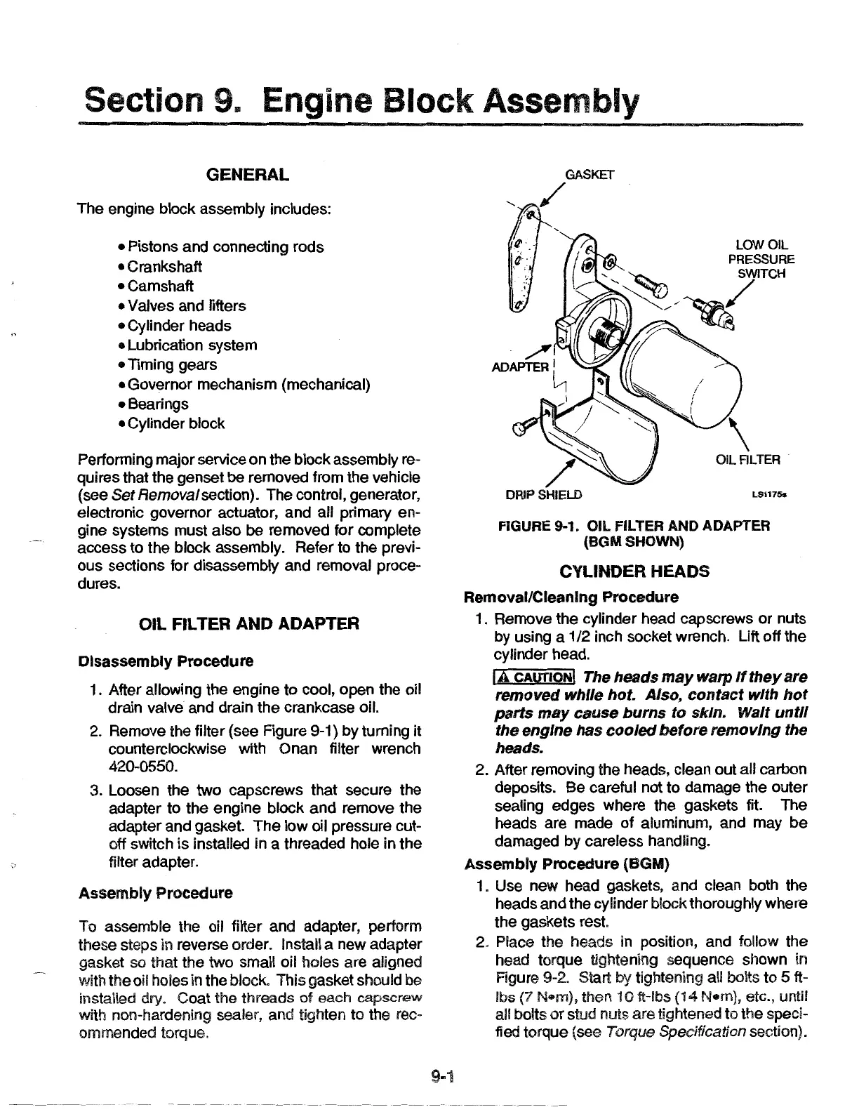
2. Remove the filter (see Figure 9-1) by turning it
counterclockwise with Onan filter wrench
420-0550.
3. Loosen the two capscrews that secure the
adapter to the engine block and remove the
adapter and gasket. The low oil pressure cut-
off switch is installed in a threaded hole in the
filter adapter.
Assembly
Procedure
To assemble the oil filter and adapter, perform
these steps in reverse order. Install a new adapter
gasket
so that the two small oil holes are aligned
with the oil holes
in the block. This gasket should be
installed dry. Coat the threads of
each
capscrew
with non-hardening sealer, and tighten to the rec-
ommended torque.
9-1
OIL ALTER
LS1175s
FIGURE 9-1. OIL FILTER AND ADAPTER
(BGMSHOWN)
CYLINDER HEADS
Removal/Cleaning
Procedure
1. Remove the cylinder head capscrews
or
nuts
by using a
1/2 inch socket wrench. Lift off the
cylinder head.
lA
CAUTION
I The heads
may
warp
If
they
are
removed while hot. Also,
contact
with
hot
parts
may
cause
burns
to skin. Walt
until
the engine has
cooled
before removing the
heads.
2. After removing the heads, clean out all carbon
deposits. Be careful not to damage the outer
sealing edges where the gaskets fit. The
heads are made
of
aluminum, and may be
damaged by careless handling.
Assembly
Procedure
(BGM)
1. Use new head gaskets, and clean both the
heads and the cylinder block thoroughly where
the gaskets rest.
2. Place the heads in position, and follow the
head torque tightening sequence shown in
Figure
9-2. Start by tightening all bolts to 5 ft-
lbs {7
N•m),
then
10
fHbs
(14
N•m),
etc., until
all bolts
or
stud nuts are tightened to the speci-
fied torque (see
Torque Specification section).
 Loading...