...
2. Push the governor rod gently
towa~ds
the car-
buretor (full-throttle position). While keeping it
there, turn the socket, as necessary, to
lengthen
or
shorten the rod so that the ball and
socket line up.
Iii
CAUTION! Too
much
pressure
on
the
rod
can
result
in
a
faulty
adjustment
of
the
rod
length.
3.
Snap the socket back over the ball.
4.
Tighten the lock nut while holding the socket
square with the axis of the ball. Also, the leg at
the throttle end of the rod must be kept level.
5.
Gently rotate the governor arm and check for
binding. If necessary, loosen the locknut and
repeat Step 4 until the linkage moves smoothly.
Binding can cause erratic governor action.
Note: The
following
groups
of
adjustments
must
be
performed
in
sequence.
They
apply
to
Spec A only.
Idle Speed
Stop
Adjustment:
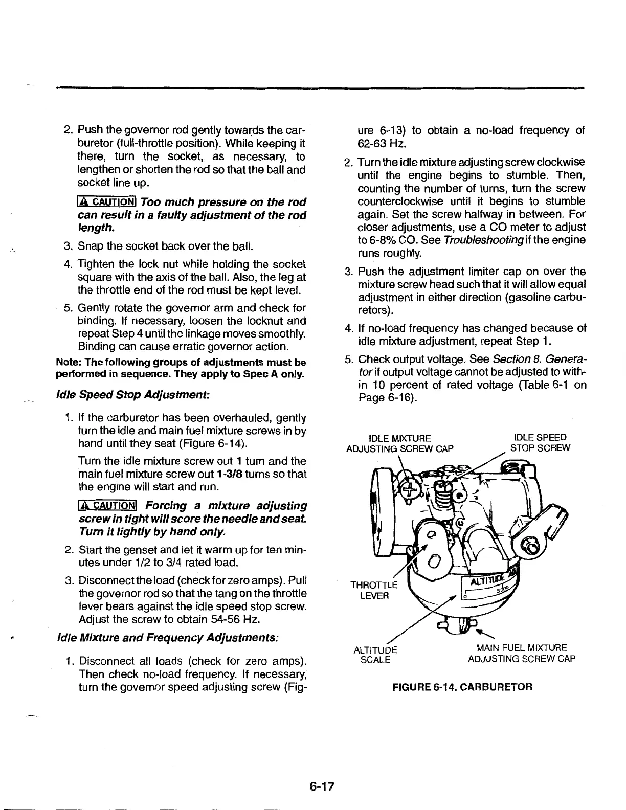
1.
If the carburetor has been overhauled, gently
turn the idle and main fuel mixture screws in by
hand until they seat (Figure 6-14).
Turn the idle mixture screw out 1 turn and the
main fuel mixture screw out 1-3/8 turns so that
the engine will start and run.
Iii
CAUTION! Forcing a
mixture
adjusting
screw
in
tight
will
score
the needle
and
seat.
Turn
it
lightly
by
hand
only.
2.
Start the genset and let it warm up for ten min-
utes under 1/2 to 3/4 rated load.
3.
Disconnect the load (checkforzeroamps). Pull
the governor rod so that the tang on the throttle
lever bears against the idle speed stop screw.
Adjust the screw to obtain 54-56 Hz.
Idle Mixture
and
Frequency
Adjustments:
1.
Disconnect all loads (check for zero amps).
Then check no-load frequency. If necessary,
turn the governor speed adjusting screw (Fig-
6-17
ure 6-13) to obtain a no-load frequency of
62-63Hz.
2. Turn the idle mixture adjusting screw clockwise
until the engine begins to stumble. Then,
counting the number of turns, turn the screw
counterclockwise until it begins to stumble
again. Set the screw halfway in between. For
closer adjustments, use a CO meter to adjust
to 6-8% CO. See
Troubleshooting if the engine
runs roughly.
3.
Push the adjustment limiter cap on over the
mixture screw head such that it will allow equal
adjustment
in
either direction (gasoline carbu-
retors).
4.
If no-load frequency has changed because of
idle mixture adjustment, repeat Step
1.
5.
Check output voltage. See Section
8.
Genera-
tor
if
output voltage cannot be adjusted to with-
in 1 0 percent of rated voltage (Table
6-1
on
Page 6-16).
IDLE MIXTURE
ADJUSTING SCREW CAP
ALTITUDE
SCALE
IDLE SPEED
STOP SCREW
MAIN FUEL MIXTURE
ADJUSTING SCREW CAP
FIGURE 6-14. CARBURETOR
 Loading...