For
Gensets
Prior
to
Spec F: Adjust lock-off
pressure as follows:
• If the lock-off pressure
is
greater than 0.25
inches (6.4 mm)
we,
remove the locking
screw and back out the adjusting screw
(counterclockwise) until the lock-off pres-
sure falls between 0.15 and 0.25 inch
we
(3.8 and 6.4 mm WC). Set the locking
screw and test lock-off pressure again.
Repeat the procedure if necessary.
• If the lock-off pressure
is
less than 0.15
inch (3.8 mm)
we,
remove the locking
screw and turn
in
the adjusting screw
(clockwise) until the lock-off pressure falls
between 0.15 and 0.25 inch
we
(3.8 and
6.4 mm WC). Set the locking screw and
test lock-off pressure again. Repeat the
procedure if necessary.
• Replace the demand regulator if it contin-
ues to leak after lock-off pressure adjust-
ments have been attempted.
4.
If the genset is mounted
in
a compartment,
make sure the vent/pressure-balance hose
is
routed properly to the outside.
5.
Reconnect the hose to the carburetor, discon-
nect any jumpers which may have been used
to energize the fuel solenoid and thread
in
and
tighten the pressure test port plug.
6.
For gensets prior to Spec
F,
adjust fuel mixture
as instructed under GOVERNOR AND CAR-
BURETOR ADJUSTMENTS
in
this section.
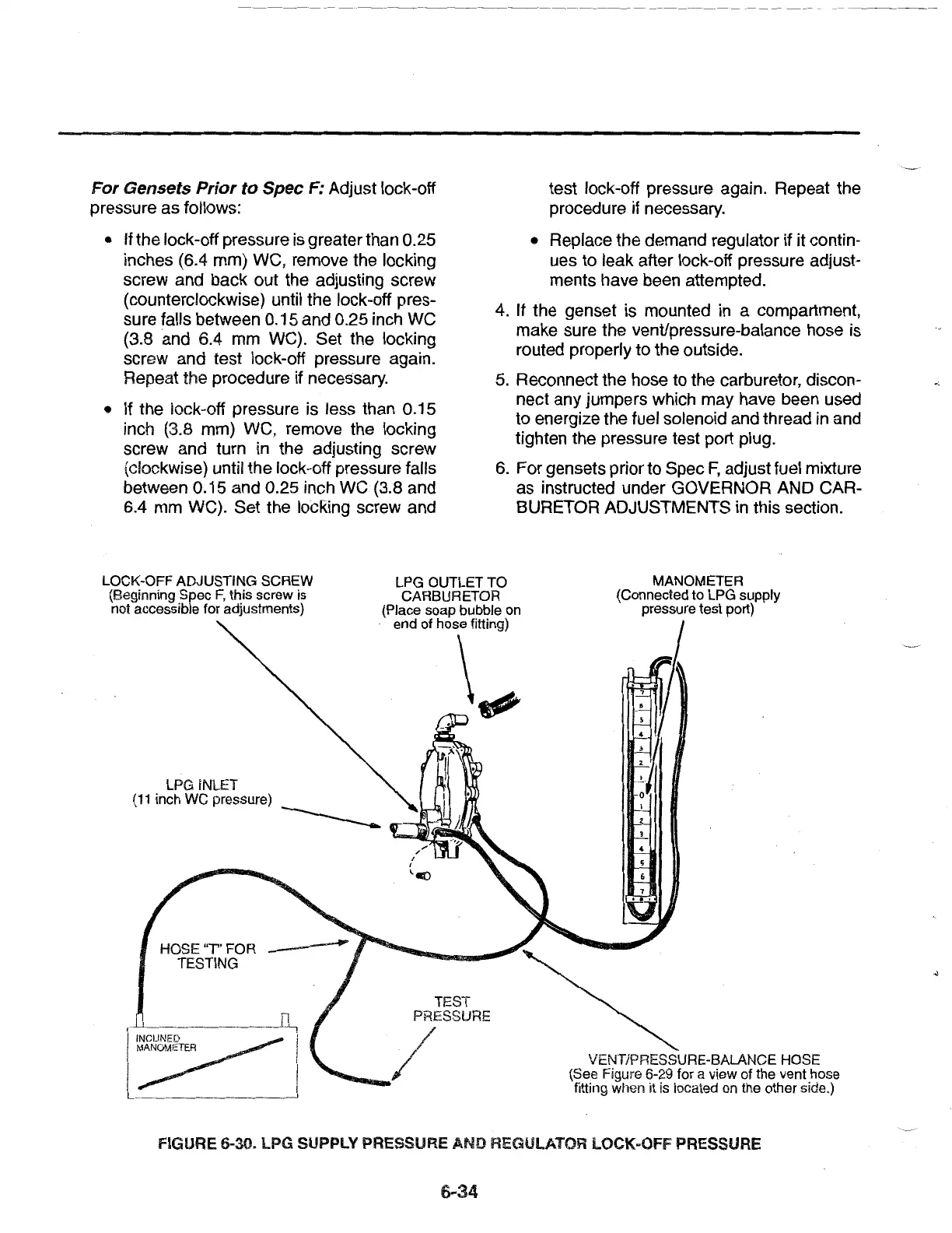
LOCK-OFF ADJUSTING SCREW
(Beginning Spec
F,
this screw is
not accessible for adjustments)
LPG OUTLET TO
CARBURETOR
(Place soap bubble on
end of hose fitting)
MANOMETER
(Connected to LPG supply
pressure test port)
\t?
LPG iNLET
(11
inch
we
pressure)
------
----t:.\-..;';j
HOSE
'T'
FOR
TESTING
~
TEST
PRESSURE
/
/'
- /
VENT/PRESSURE-BALANCE HOSE
(See Figure 6-29 for a view of the vent hose
fitting when it
is
located
on
the other side.)
FIGURE 6-30. LPG
SUPPlY
PRESSURE AND REGULATOR LOCK-OFF PRESSURE
6-34
..)
 Loading...