Removing the
Roll
Pin: Remove the return spring,
gear and clutch assembly if necessary by driving
out the roll pin. Use a 1/8 to 5/32 inch nail set (Figure
6-32). Always use a
new
roll pin when reassembling
the drive assembly.
5/32-1/8
inch
NAIL
SET
ROLL
PIN
SUPPORT PLASTIC RETAINER WITH A VISE OR OTHER
SOLID SURFACE. USE CARE NOT TO HAVE SPRING
RETURN "LEG" BETWEEN THE PLASTIC RETAINER
AND SUPPORT WHEN DRIVING OUT ROLL PIN
FIGURE 6-32. REMOVING
ROLL
PIN
Testing and Inspecting the Starter
Testing
Armature
for
Grounds: Touch one ohm-
meter
lead to a commutator bar, then touch the oth-
er lead
to
the armature shaft and the core lamina-
tions (Figure 6-33).
A
low
resistance reading indi-
cates a grounded armature. Replace a grounded
armature with a
new
one.
COMMUTATOR
BARS
FIGURE 6-33. TESTING ARMATURE FOR
GROUNDS
6-36
Testing Armature
for
Shorts: Use a growler (Fig-
ure 6-34) to locate shorts in the armature. Place the
armature
in
the growler and hold a thin steel blade
(hacksaw blade) parallel to the core and just above
the armature, while slowly rotating the armature in
the growler.
A shorted armature will cause the blade
to
vibrate and be attracted
to
the
core. Replace a
shorted armature with a
new
one.
HACKSA~
FIGURE 6-34. TESTING ARMATURE FOR SHORTS
Testing Armature
for
Opens: Touch one ohmme-
ter lead to a commutator bar, then touch the other
lead to each
of
the other commutator bars in turn. A
high resistance indicates an open circuit between
the commutator bars and armature windings. Re-
place an open armature with a
new
one.
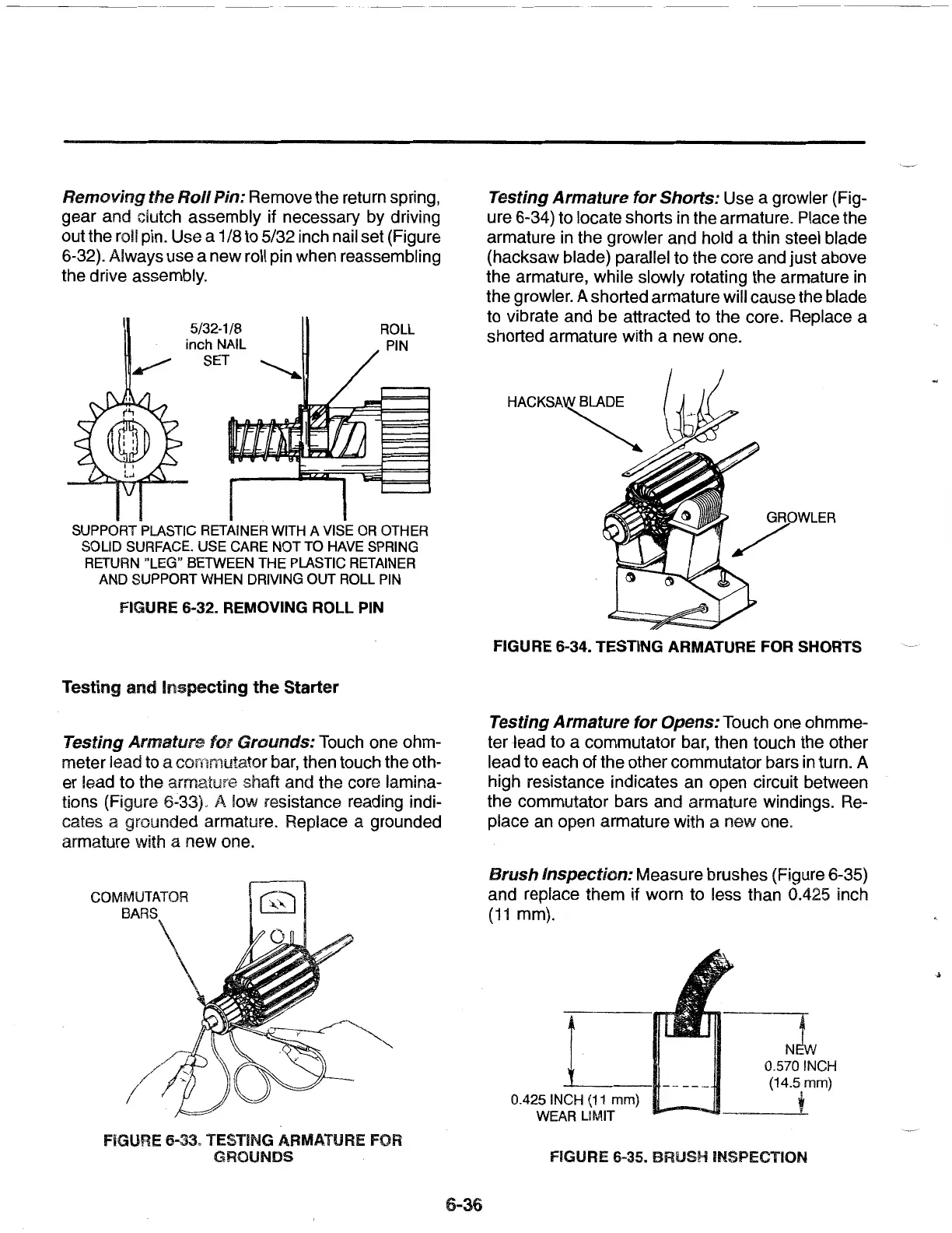
Brush
Inspection: Measure brushes (Figure 6-35)
and replace them
if
worn to less than 0.425 inch
(11
mm).
0.425 INCH
(11
mm)
WEAR LIMIT
N
0.570 INCH
(14.5 mm)
+
FIGURE 6-35. BRUSH INSPECTION
 Loading...