11.
Place the mounting bracket on the motor, fac-
ing the exposed end of the sleeve bearing and
through-bolt lead-ins toward the inside of the
motor. The flat near one mounting hole should
line up with the positive stud on the end cap, so
the through-bolts can line up.
12. Insert the through-bolts, and torque to 35-45
lbs-in (3.96-5.09 N-m).
13. Wipe dust from the helix and gear, and apply a
light coat
of
GE
Versilube 322-L
to
the outside
diameter of the helix, the inside diameter of the
gear and the unchamfered end of the gear.
Place the clutch and helix assemblies on the
motor shaft, with flats engaged in the clutch
hole.
14. If the return spring is unassembled,
do
the fol-
lowing:
A. Place a 1-1/16 inch O.D. washer over the
end
of
the shaft.
B.
With the chamfered side of the shaft hole
facing up, place a plastic retainer on the
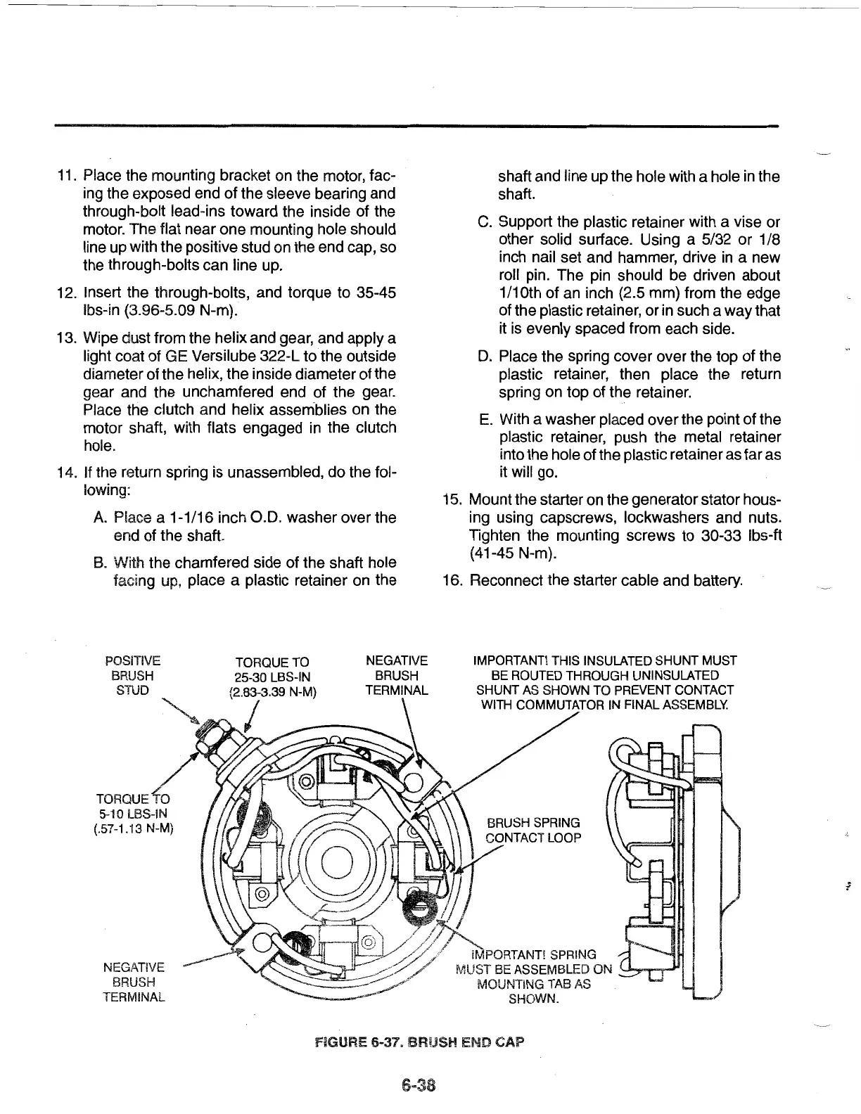
POSiTIVE
BRUSH
STUD
/
TORQUE
TO
5-10 LBS-iN
(.57-1.13 N-M)
NEGATIVE
BRUSH
TERMINAL
TORQUE
TO
25-30 LBS-IN
(2.83-3.39 N-M)
I
NEGATIVE
BRUSH
TERMINAL
shaft and line up the hole with a hole in the
shaft.
C.
Support the plastic retainer with a vise
or
other solid surface. Using a 5/32
or
1/8
inch nail set and hammer, drive in a new
roll pin. The pin should be driven about
1/10th of an inch {2.5 mm) from the edge
of the plastic retainer,
or
in such a way that
it is evenly spaced from each side.
D.
Place the spring cover over the top of the
plastic retainer, then place the return
spring on top of the retainer.
E.
With a washer placed over the point of the
plastic retainer, push the metal retainer
into the hole of the plastic retainer
as
far as
it will go.
15. Mount the starter on the generator stator hous-
ing using capscrews, lockwashers and nuts.
Tighten the mounting screws to 30-33 lbs-ft
(41-45 N-m).
16. Reconnect the starter cable and battery.
IMPORTANT!
THIS
INSULATED SHUNT MUST
BE
ROUTED
THROUGH UNINSULATED
SHUNT
AS
SHOWN
TO
PREVENT
CONTACT
WITH
COMMUTATOR
IN
FINAL
ASSEMBLY.
IMPORTANT! SPRING
MUST
BE
ASSEMBLED
ON
~..J...,,...,-..,
i'v10UNTING
TAB
AS
SHOWN.
FiGURE 6-37. BRUSH END CAP
 Loading...