Do you have a question about the Onkyo Grand Integra and is the answer not in the manual?
Describes the amplifier's power output and distortion levels.
Details the power supply design for driving low impedance loads.
Explains the isolation of circuit blocks to minimize interference.
Highlights dual D/A converters with Opto-Drive for audio quality.
Mentions Opto-Drive in the differential amplifier stage for distortion-free signal.
Crucial safety warnings to prevent fire and electric shock.
Guidance on using polarized plugs safely with extension cords.
Instructions for wiring replacement power cords for specific models.
Guidelines for placement, ventilation, and avoiding heat sources.
Details on warranty card, copyright laws, and AC fuse location.
Procedures for cleaning and important notes on power supply voltage.
Explains jack correspondence, color-coding, and short pin usage.
Details connections for turntables, tuners, CD players, DAT, and digital sources.
Covers connections for video components, VCRs, and audio processors.
Guides on connecting VCRs, VDPs, and monitor TVs.
Explains connections for pre-amplifiers, power amplifiers, and digital audio.
Instructions for connecting speakers and safety notes for banana plugs.
Information on switched/unswitched AC outlets and TV interference.
Describes the function and indicator of the power switch.
Location and function of the sensor for remote control signals.
Controls for bypassing circuits and selecting input sources.
Adjusts volume and reduces sound level for easier adjustment.
Selectors for choosing between digital, CD, PHONO, and TUNER inputs.
Selectors for analog/digital recording and video playback modes.
Switches for Pre-Out, Processor, and tone adjustments.
Ports for headphones and selector for multiple speaker systems.
Initial settings for front panel controls in standby mode.
Instructions for listening to CD, records, broadcasts, and tape decks.
Guides for playing back video components and digital audio devices.
Procedures for recording from various sources to tape decks or DAT.
Steps for DAT digital recording and using processor jacks for monitoring.
Guides for VDP to VCR recording and Background Video playback.
Instructions for using mixing consoles or graphic equalizers for sound tuning.
Connects PRE OUT jacks to a power amplifier for sound output.
Connects PRE OUT jacks to a power amplifier, controlling volume from this unit.
Connects MAIN IN jacks to a pre-amplifier for independent use.
Instructions for inserting and replacing batteries in the remote control.
Details on volume control and absolute phase adjustment via remote.
Notes on battery removal, infrared interference, and optimal range.
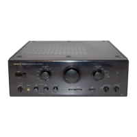
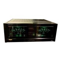
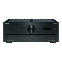
The Onkyo Grand Integra A-G10 is an integrated stereo amplifier designed to deliver high-quality audio performance. It boasts a robust power output of 135 watts per channel into 8 ohms, ensuring clean and continuous power delivery with remarkably low total harmonic distortion. Its capability to drive low impedance loads is a key feature, with dynamic power rated at 2 x 460 watts into 2 ohms, making it suitable for a wide range of speaker systems.
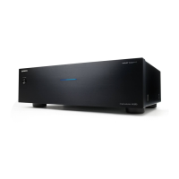
A significant aspect of the A-G10's design is its oversized power supply block, engineered to provide abundant power reserves for faithfully reproducing today's wide dynamic range digital sources. This is achieved through the use of high-quality components, including five separate windings on the secondary side of a massive main power transformer, which provide independent voltages for each of the separate analog circuit blocks. A dedicated power transformer is used for the digital block of the D/A converter. The left and right channel rectifier blocks feature high-speed switching diodes and a total of eight high-current split chemical capacitors, all contributing to its impressive performance.
The amplifier employs a modular construction, isolating its four principal circuit blocks to minimize electromagnetic interference. The massive left and right channel power supply blocks are strategically placed close to the output jacks and heavily shielded. The Opto-Driven D/A converter and digital processing blocks are located on the opposite side of the chassis and are encased in separate copper-plated, electromagnetically shielded cases.
Built-in dual 18-bit D/A converters with Opto-Drive allow users to route digital output from CD and DAT players directly into the A-G10, with both optical and electrical input jacks provided. These converters are designed to convert digital input into a pure, distortion-free music signal. Separate converters for the left and right channels eliminate phase shifting, particularly in high frequencies. The 18-bit D/A conversion offers improved linearity and higher resolution compared to 16-bit systems, which is especially beneficial for delicate low-level signals. The A-G10 also incorporates Onkyo's exclusive Opto-Drive in the crucial differential amplifier stage of its power amplifier circuitry, ensuring a music signal free of distortion caused by electromagnetic interference.
The front panel of the A-G10 features a Power Switch with an indicator, a Remote Control Sensor for receiving signals, and a Source Direct Switch. When the Source Direct switch is engaged, the volume of the selected source is input directly into the main amplifier, bypassing tone control, muting, balance, mode, processor, and absolute phase circuits, with the indicator lighting up. When off, these functions can be altered. A Muting Switch reduces sound volume by approximately 1/10 (-20dB) for easier low-volume adjustment. The Volume Control Knob allows for manual volume adjustment and can also be operated via remote control. This volume control utilizes a Variable Tone Boosting System, which gradually reduces the effect of tone controls (contrabass, bass, and treble) as the volume increases beyond a certain level, ensuring a flat frequency response at maximum volume.
Digital input selection is managed by a Digital Input Selector Switch and Indicator, allowing the unit to be set to various digital sources like COAXIAL DIGITAL 1 (for audio components), DIGITAL 2 (for DAT), and OPTICAL DIGITAL 3 (for audio components). The Input Selector Switch and Indicator allow selection of various analog sources such as VCR, VDP, TAPE, DAT, PHONO (MM/MC), and TUNER.
For recording, the Analog Recording Source Selector Switch (DAT/TAPE ANALOG REC) allows selection of recording sources for tape dubbing. A Digital Recording Source Selector Switch (DIGITAL REC) enables digital recording from selected digital input sources. The Digital Lock indicator shows that a digital signal is being input, changing color based on the sampling frequency (32kHz orange, 44.1kHz green, 48kHz red). The Video Mode Switch (VIDEO MODE) allows selection of VCR recording sources and Background Video (BGV) sources.
For USA, Canadian, and Worldwide models, an Amp Selector Switch (PRE/MAIN) can separate the pre-amp section from the power amp section for individual use. An Absolute Phase Indicator, controllable via remote, allows phase reversal. A Processor On/Off Switch enables units connected to the PROCESSOR jacks. A Cartridge Selector Switch (CARTRIDGE) matches the type of phono cartridge (MC or MM). The Mode Selector Switch (MODE) offers STEREO for normal listening and MONO for monaural recordings or balance adjustment. Balance, Treble, Bass, and Contrabass Control Knobs allow for sound adjustment, with DEFEAT positions bypassing the tone control circuitry. A Headphone Jack (PHONES) is provided for stereo headphones. The Speaker Selector Switch (SPEAKERS) allows activation of one or two pairs of speaker systems, or only headphones.
Maintenance features include precautions for optimal performance and longevity. Users are advised to avoid direct sunlight, extreme temperatures, damp or dusty places, and vibrations from speakers. Proper ventilation is crucial, and the unit should not be placed in enclosed spaces that impede airflow. Heat sources should be avoided. Internal parts should only be cleaned by qualified service personnel. Care should be taken to prevent objects from falling or liquids from spilling into the unit. In case of damage or malfunction, servicing should be referred to qualified service personnel.
For power cords without plugs (British models), replacement and mounting of an AC plug should be performed by qualified service personnel, following specific wiring codes. For models with a polarized plug, caution is advised to prevent electric shock. Worldwide models feature a Voltage Selector on the rear panel to conform with local power supplies, which must be set correctly before turning on the power.
The remote control transmitter (for U.S.A., Canadian, and Worldwide models) is powered by two AA batteries. Users are instructed on how to replace batteries, with precautions against using expired, mismatched, or rechargeable batteries. The remote control includes Volume Keys and an Absolute Phase Key. Precautions for remote control use include removing batteries during long periods of disuse, periodic replacement, avoiding bright light exposure to the unit's front panel, and ensuring no interference from other infrared devices. If the remote control malfunctions, checking batteries and restarting the unit after a brief power-off period is recommended.
| impedance (phono MC) | 110 1V/100 ohms |
|---|---|
| power output | 1435 watts per channel |
| total harmonic distortion | 0.008% |
| dynamic power at 4 ohms | 240 watts |
|---|---|
| dynamic power at 2 ohms | 155 watts |
| dynamic power at 8 ohms | 310 watts |
| frequency response CO, Tuner | 2 Hz-50 kHz |
|---|---|
| signal to noise ratio (source direct) | 104 dB |
| signal to noise ratio (phono MM) | 89 dB |
| weight | 30 kg, 66.1 lbs |
|---|---|
| dimensions (W x H x D) | 477 mm x 183 mm x 453 mm |