12
Example of how to connect your equipment
Here is explanation of how to connect the main components to the
HT-R490 in the standard manner. There are many ways that any
one component can be connected, and it is up to you to decide
which method best fits your situation. The directions given here
are only one option and should only be thought of as such. It is best
to fully understand the nature of each connector and terminal as
well as each of your components and their features to ascertain
which method of connection is best.
• Be sure to always refer to the instruction manual that came
with the component that you are connecting.
• Do not plug in the power cord until all connections have been
made.
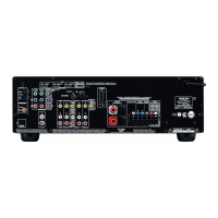
• For input jacks, red connectors (marked R) are used for the
right channel, white connectors (marked L) are used for the
left channel, and yellow connectors (marked VIDEO) are used
for video connection.
• Insert all plugs and connectors securely. Improper connections
can result in noise, poor performance, or damage to the
equipment.
• Do not bind audio connection cables with power cords and
speaker cables. Doing so may adversely effect the sound
quality.
For a detailed explanation of how to connect the devices given
below, refer to the pages listed.
Speakers: See page 17
Radio antenna: See page 18
Setting the digital inputs
When connecting digital source components to the DIGITAL
INPUT jacks on the rear panel, assign the input source button on
the front panel to either a DIGITAL INPUT OPTICAL or
COAXIAL jack depending on the type of connector on the digital
source components. The DVD, CD, VIDEO 1, VIDEO 2 and
TAPE inputs can be assigned to the DIGITAL INPUT jacks.
With the initial setting, the OPTICAL jack is assigned to the CD
input, COAXIAL jack is assigned to the DVD input, and no input
connector is assigned to the VIDEO 1, VIDEO 2 and TAPE inputs.
– – – – – :
Available for digital input but not set in initial setting.
: Not available for digital input.
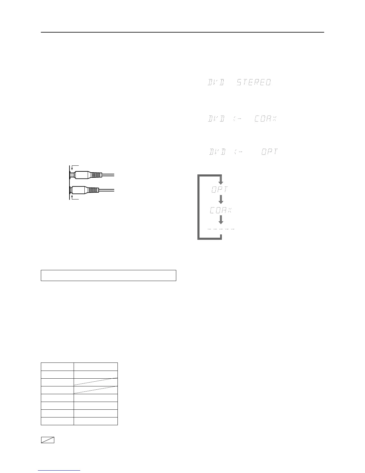
For example, follow the steps below to assign OPTICAL to the
DVD device connected to the DIGITAL INPUT OPTICAL jack.
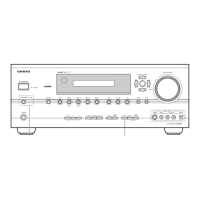
1. Press the DVD Input Selector button.
The DVD input is selected and “DVD” appears in the display.
2. Press the DIGITAL INPUT button.
The current DVD setting (COAX) appears.
3. Press the DIGITAL INPUT button repeatedly to
select “OPT”.
Pressing the DIGITAL INPUT button repeatedly will change
the setting as follows:
Improper connection
Inserted completely
Select if connected to DIGITAL INPUT
OPTICAL.
Select if connected to DIGITAL INPUT
COAXIAL.
Select if the input source is not from a
digital input jack.
Default setting
Input source Digital input
CD OPTICAL
AM
FM
TAPE – – – – –
VIDEO 2 – – – – –
VIDEO 1 – – – – –
DVD COAXIAL
About five seconds after “OPT” is selected, the original
display appears and the setting is completed.
If you have selected digital input, you can also select the input
signal format (refer to “Setting the input signal format” on
page 23).
Note:
Do not assign a single DIGITAL INPUT jack to more than one
source.
For example, if you assign the OPTICAL jack to the DVD input,
since the OPTICAL jack is assigned to the CD input by the initial
setting, it would result in assigning a single OPTICAL jack to both
the CD and DVD inputs.
Whenever you assign a DIGITAL INPUT jack to a different
source from the initial setting, be sure to change the initial setting
for the jack in advance.
 Loading...