Supplied accessories
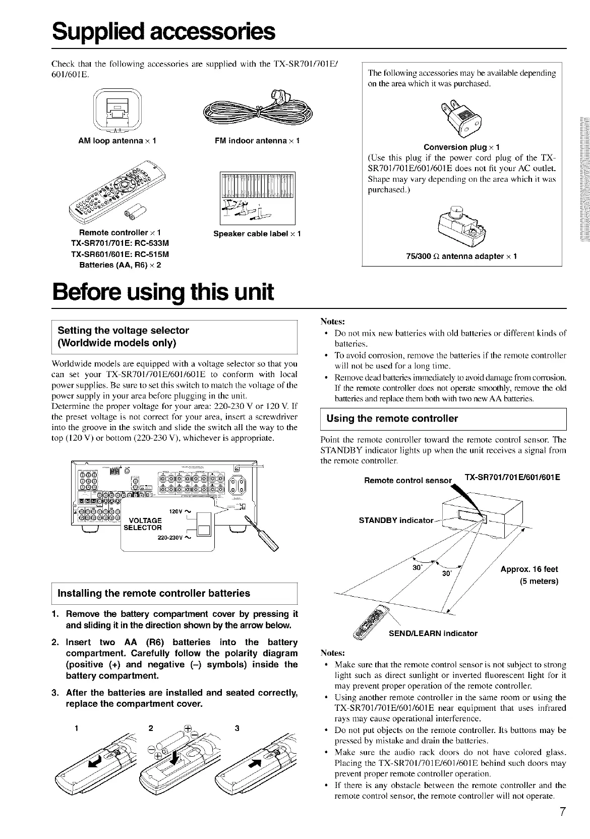
AM loop antenna × 1
Check that the following accessories are supplied with the TX-SR701/701E/
601/601E.
FM indoor antenna × 1
Remote controller × 1
TX-SR701/701 E: RC-533M
TX-SR601/601 E: RC-515M
Batteries (AA, R6) x 2
Speaker cable label × 1
The following accessories may be available depending
on the area which it was purchased.
Conversion plug × 1
(Use this plug if the power cord plug of the TX-
SR701/701E/601/601E does not fit your AC outlet.
Shape may vary depending on the area which it was
purchased.)
75/300 _2 antenna adapter × 1
Before using this unit
Setting the voltage selector
(Worldwide models only)
Worldwide models are equipped with a voltage selector so that you
can set your TX-SR701/701E/601/601E to conform with local
power supplies. Be sure to set this swilch to mateh the voltage of the
power supply in your area before plugging in the unit.
Determine the proper voltage for your area: 220-230 V or 120 V. If
the preset voltage is not correct for your area, insert a screwdriver
into the groove in the switch and slide the switch all the way to the
top (I 20 V) or bottom (220-230 V), whichever is appropriate.
120V
VOLTAGE
_ELECTOR
220-230V "%'
Notes:
• Do not mix new batteries with old batteries or different kinds of
batteries.
• To avoid corrosion, remove the batteries if the remote controller
will not be used for a long time.
• Remove dead batteries imnaediately te avoid damage from corrosion.
If the remote controller does not operate smoothly, remove the old
batteries and replace them/x)th with two new AA batteries,
I Using the remote controller
Point the remote controller loward the relnote control sensor. The
S'IANDBY indicator lights up when the unit receives a signal from
the remote controller.
Remote control sensor TX-SR701/701FJ601/601E
Installing the remote controller batteries
1. Remove the battery compartment cover by pressing it
and sliding it in the direction shown by the arrow below.
2. Insert two AA (R6) batteries into the battery
compartment. Carefully follow the polarity diagram
(positive (+) and negative (-) symbols) inside the
battery compartment.
3. After the batteries are installed and seated correctly,
replace the compartment cover.
1 2 A_ 3
/
_SEND/LE_AARN indicator
Approx. 16feet
(5meters)
Notesl
• Make sure thaI the remote control sensor is not sul2ject to strong
light such as direct sunlight or inverted fluorescent light for it
may prevent proper operation of the remote controller.
• Using another remote controller in the same room or using the
TX-SR701/701E/601/601E near equipment that uses infrared
rays may cause operational interference.
• Do not put objects on the remote controller. Its buttons may be
pressed by mistake and drain the balteries.
• Make sure the audio rack doors do not have colored glass.
Placing the TX-SR7OI/701E/601/601E behind such doors may
prevent proper remote controller operation.
• If there is any obstacle between the remote controller and the
remote control sensor, the remote controller will not operate.
7