IC BLOCK DIAGRAMS AND TERMINAL DESCRIPTIONS -33
Q8001 : SII504 (I/P Video Converter)
TX-SR674/674E/8467
Signal Group
Signal Name
Notes
Type
Description
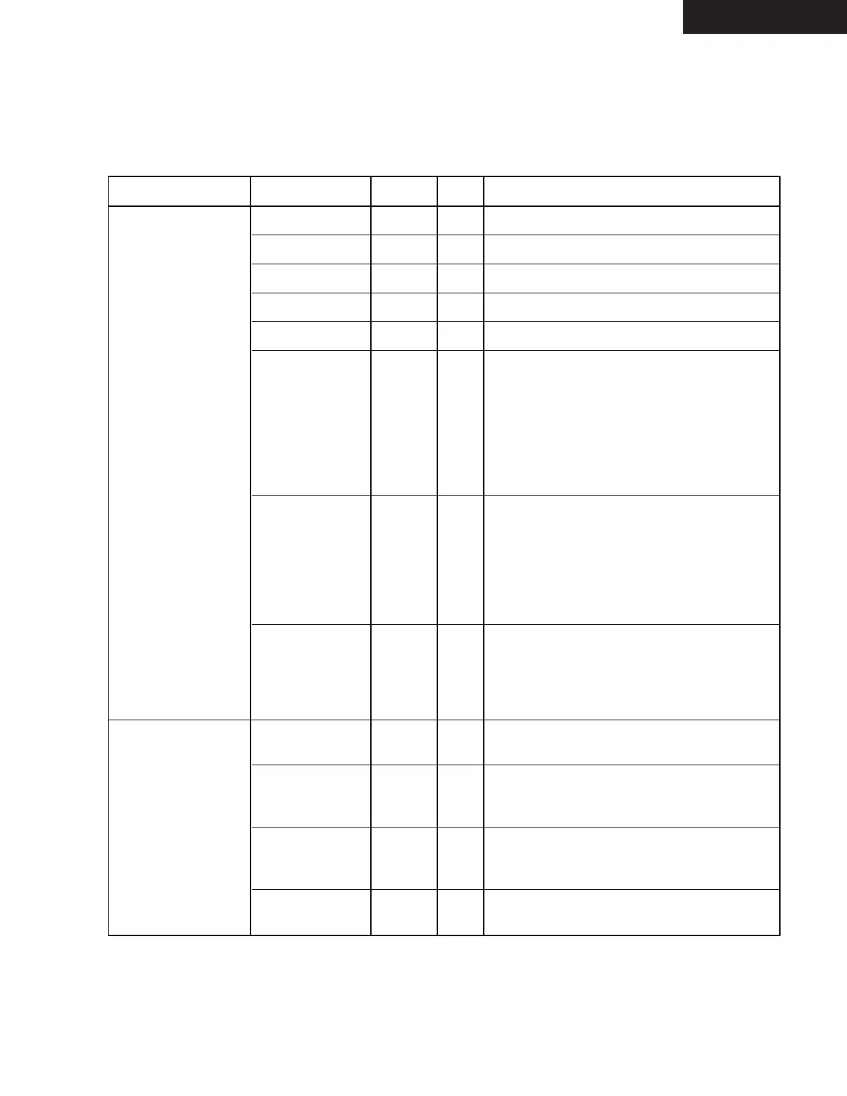
Memory /RAS Out SDRAM Row Address Strobe.
/CAS Out
SDRAM Column Address Strobe.
/WE Out
SDRAM Write Enable.
DQM Out
SDRAM Data Mask.
MemData[31:0] 5V InOut
SDRAM Data.
MemAddr[12:0] 5V/PU/PD InOut SDRAM Address when an output.
Configuration at reset when and input.
See Memory Subsystem an Hardware
Configuration sections of Functional
Description for details. (Note: MemAddr12
is an output-only pin, does not have an
internal pullup or pulldown, and is not part
of the startup configuration.)
MemClk 5V InOut SDRAM Clock. Normally, this pin is an InOut,
outputting an internal PLL-generated 66.0
MHz or 72.0 MHz clock to the SDRAM and
receiving that same clock through its input
buffer. To bypass the PLL, set
/BypPLLMemClk = 0, and supply a 66.0 MHz
or 72.0 MHz clock to MemClk.
/BypPLLMemClk 5V/PU In Bypass PLL for MemClk. Normally, this pin is
a no-connect, and the internal pullup ensures
that the PLL is enabled. To bypass the PLL,
set /BypPLLMemClk = 0, and suppy a 66.0
MHz or 72.0 MHz clock to the MemClk pin
Host Interface /HostWr_SCL 5V/H In 186-Compatible Write when HostMode = 0.
Serial Clock when HostMode = 1.
/HostRd_SDA 5V/H InOut 186-Compatible Read when HostMode = 0.
Serial Data (InOut, open drain output) when
HostMode = 1.
/HostCS 5V/PU In 186-Compatible Chip Select when
HostMode=0. When HostMode=1, must be
tied to VDD or pulled up to VDD.
HostAddr[7:0] 5V/PD In
186-Compatible Address when HostMode = 0.
No connect when HostMode = 1.
TERMINAL DESCRIPTION (3/5)