5 The solenoid contacts can be checked by
connecting a voltmeter or test lamp between
the battery positive feed connection on the
starter side of the solenoid, and earth. When
the ignition switch is turned to the `start’
position, there should be a reading or lighted
bulb, as applicable. If there is no reading or
lighted bulb, the solenoid is faulty and should
be renewed.
6 If the circuit and solenoid are proved
sound, the fault must lie in the starter motor.
In this event, it may be possible to have the
starter motor overhauled by a specialist, but
check on the cost of spares before
proceeding, as it may prove more economical
to obtain a new or exchange motor.
Removal
1 Disconnect the battery earth lead.
1.2 litre models
2 Disconnect the battery positive leads;
separate the starter motor lead from the other.
Also disconnect the positive lead from the
alternator.
3 Separate the gearshift linkage to improve
access. Unbolt and remove the starter motor
from above, disconnecting the solenoid
command lead.
4 If a new starter motor is being fitted,
transfer the electrical lead to it.
1.4, 1.6, 1.8 and 2.0 litre 8-valve
models
5 Raise and support the front of the vehicle
(see “Jacking and Vehicle Support”).
6 Note the electrical connections to the
starter solenoid, then disconnect them.
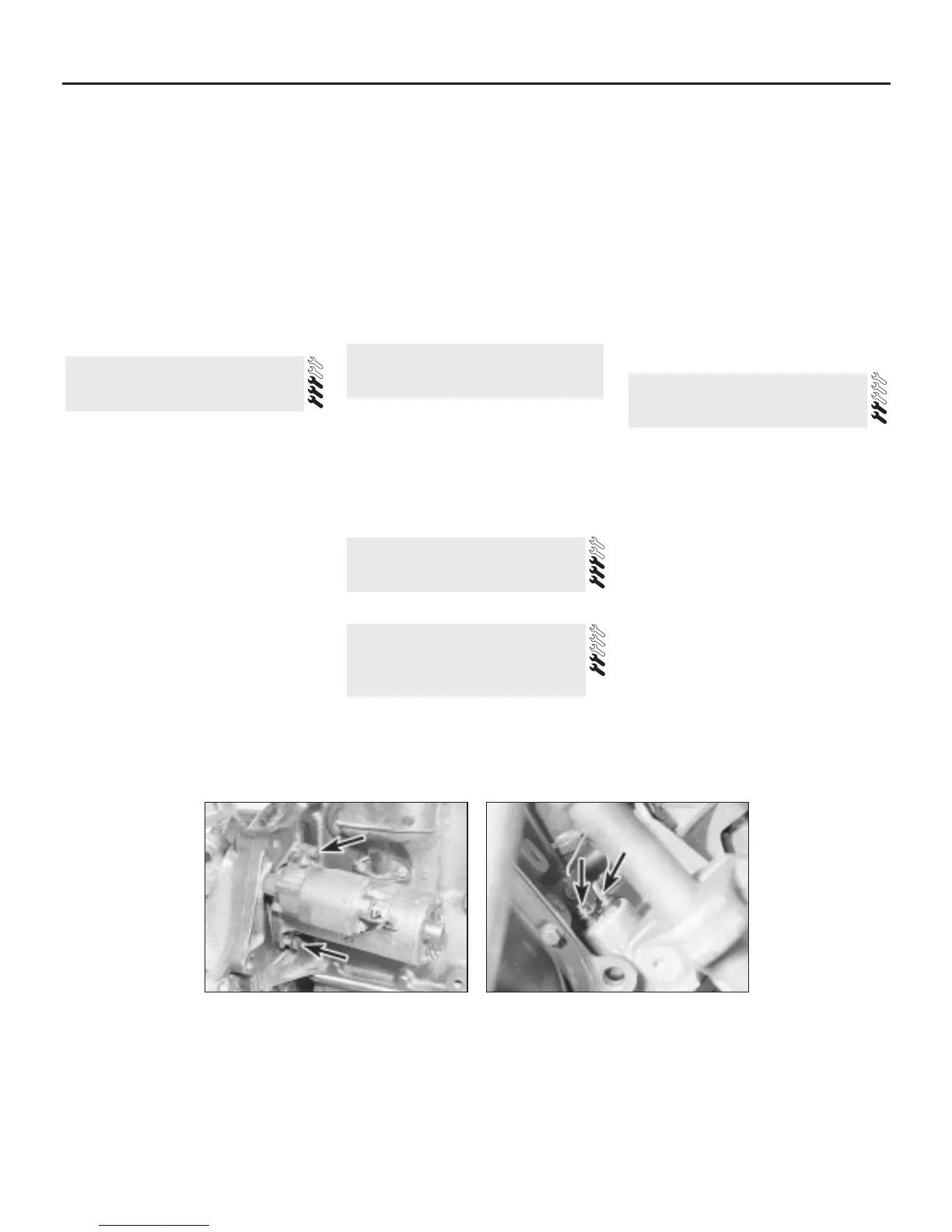
7 Unbolt the starter motor and remove it from
below (see illustration).
2.0 litre 16-valve models
8 Remove the starter motor-to-transmission
bolts which are accessible from above.
9 Raise and support the front of the vehicle
(see “Jacking and Vehicle Support”). Remove
the inlet manifold bracing strap.
10 Disconnect the main feed and command
leads from the starter motor.
11 Remove the remaining starter motor
mounting bolts, not forgetting the bracket at
the brushgear end of the motor. Remove the
motor from below.
Refitting
12 Refitting is the reverse of the removal
procedure.
If the starter motor is thought to be suspect,
it should be removed from the vehicle and
taken to an auto-electrician for testing. Most
auto-electricians will be able to supply and fit
brushes at a reasonable cost. However, check
on the cost of repairs before proceeding as it
may prove more economical to obtain a new
or exchange motor.
Refer to Chapter 10.
Removal
1 The switch/gauge sender is screwed into
the cylinder block or oil filter carrier
(depending on model).
2 Disconnect the battery negative lead and
disconnect the wiring from the switch/sender
(see illustration).
3 Unscrew the switch/sender and recover the
sealing washer. Be prepared for oil spillage,
and if the switch is to be left removed from the
engine for any length of time, plug the hole.
Refitting
4 Examine the sealing washer for signs of
damage or deterioration and if necessary
renew.
5 Refit the switch/sender, complete with
washer, and tighten it securely. Reconnect the
wiring.
6 Check and, if necessary, top-up the engine
oil as described in Chapter 1.
Removal
1 Raise and support the front of the vehicle
(see “Jacking and Vehicle Support”).
2 Disconnect the battery earth (negative)
lead.
3 Drain the engine oil, saving it if it is fit for
re-use.
4 Follow the sensor wiring back to its
connection with the main wiring harness and
disconnect it. (Early type sensors have a
wiring plug secured with two screws, which
can be disconnected at the sensor.)
5 Remove the four screws which secure the
sensor to the sump. Remove the sensor and
recover the seal.
Refitting
6 Refitting is the reverse of the removal
procedure. Use a new seal. Refill the engine
with oil on completion.
14 Oil level sensor (16-valve
models) - removal and refitting
13 Oil pressure warning light
switch/gauge sender -
removal and refitting
12 Ignition switch - removal and
refitting
11 Starter motor - testing and
overhaul
10 Starter motor - removal and
refitting
5A•4 Starting and charging systems
10.7 Starter motor mounting bolts
(arrowed) - engine removed for clarity
13.2 Oil pressure sender wires (arrowed)

 Loading...