8 To separate the fan motor from the cowl
unscrew the three nuts. The fan blades may
be withdrawn from the motor spindle after
removal of the retaining clip.
9 Further dismantling of the assembly
depends on the extent of the problem. If the
motor is defective it would be better to have it
overhauled by a specialist, as spare parts may
be difficult to obtain. The alternative is to
renew the motor which may prove cheaper
and quicker in the long run.
Refitting
10 Reassembly, if the unit was dismantled,
and refitting to the car are the reverse of the
dismantling and removal sequences. On
completion run the engine up to normal
operating temperature and check the fan for
correct functioning.
Electric cooling fan thermostatic
switch
Testing
1 Testing of the switch is described in
Section 6, as part of the fan test procedure.
Removal
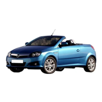
2 The switch is located in the side of the
radiator (see illustration). The coolant should
be cold before removing the switch.
3 Disconnect the battery negative lead. If
necessary, firmly apply the handbrake then
jack up the front of the vehicle and support it
on axle stands (see “Jacking and Vehicle
Support”). Access to the switch can then be
gained from underneath the vehicle.
4 Either drain the cooling system to below the
level of the switch (as described in Chapter 1),
or have ready a suitable plug which can be
used to plug the switch aperture in the
radiator whilst the switch is removed. If a plug
is used, take great care not to damage the
radiator, and do not use anything which will
allow foreign matter to enter the radiator.
5 Disconnect the wiring plug from the switch.
6 Carefully unscrew the switch from the
radiator and recover the sealing ring/washer.
Refitting
7 Refitting is a reversal of removal using a
new sealing ring/washer. Securely tighten the
switch and top-up/refill the cooling system as
described in Chapter 1.
8 On completion, start the engine and run it
until it reaches normal operating temperature,
then continue to run the engine and check that
the cooling fan cuts in and functions correctly.
Coolant temperature gauge
sender
Testing
9 The coolant temperature gauge, mounted
in the instrument panel, is fed with a stabilised
voltage supply from the instrument panel feed
(via the ignition switch and a fuse), and its
earth is controlled by the sender.
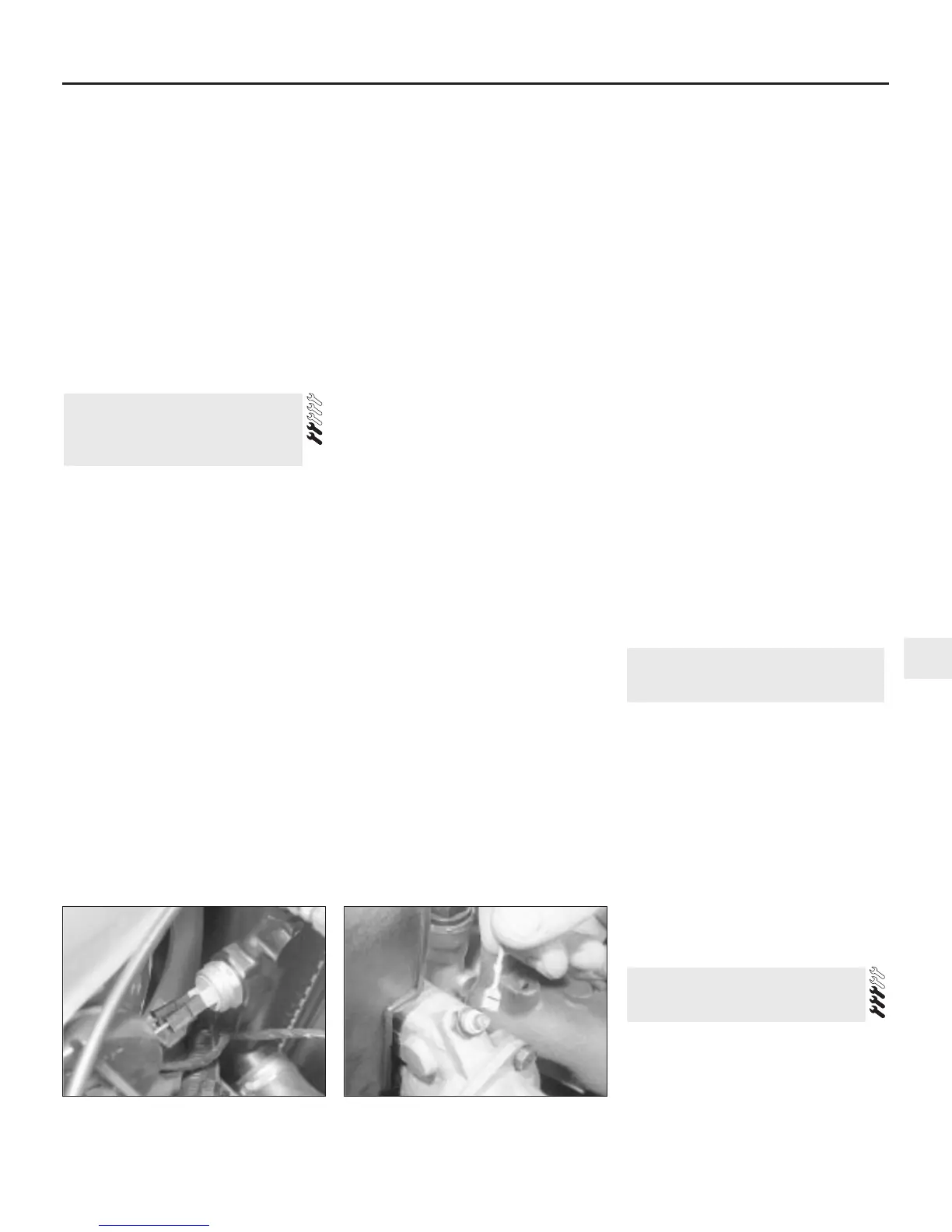
10 The sender is located in the cylinder head,
behind the water pump on 1.2 litre engines, in
the inlet manifold on 1.3 and 1.4 litre engines,
and in the thermostat housing on 1.6, 1.8 and
2.0 litre engines (see illustration). The sender
contains a thermistor, which consists of an
electronic component whose electrical
resistance decreases at a predetermined rate
as its temperature rises. When the coolant is
cold, the sender resistance is high, current flow
through the gauge is reduced, and the gauge
needle points towards the `cold’ end of the
scale. If the sender is faulty, it must be renewed.
11 If the gauge develops a fault, first check
the other instruments; if they do not work at
all, check the instrument panel electrical feed.
If the readings are erratic, there may be a fault
in the voltage stabiliser, which will necessitate
renewal of the stabiliser (see Chapter 12). If
the fault lies in the temperature gauge alone,
check it as follows.
12 If the gauge needle remains at the `cold’
end of the scale, disconnect the sender wire,
and earth it to the cylinder head. If the needle
then deflects when the ignition is switched on,
the sender unit is proved faulty, and should be
renewed. If the needle still does not move,
remove the instrument panel (Chapter 12) and
check the continuity of the wiring between the
sender unit and the gauge, and the feed to the
gauge unit. If continuity is shown, and the
fault still exists, then the gauge is faulty, and
the gauge unit should be renewed.
13 If the gauge needle remains at the `hot’
end of the scale, disconnect the sender wire.
If the needle then returns to the `cold’ end of
the scale when the ignition is switched on, the
sender unit is proved faulty and should be
renewed. If the needle still does not move,
check the remainder of the circuit as
described previously.
Removal
14 Either partially drain the cooling system to
just below the level of the sender (Chapter 1),
or have ready a suitable plug which can be
used to plug the sender aperture whilst it is
removed. If a plug is used, take great care not
to damage the sender unit threads, and do
not use anything which will allow foreign
matter to enter the cooling system.
15 Disconnect the battery negative lead.
16 Disconnect the wiring from the sender,
then unscrew the unit from its location.
Refitting
17 Ensure that the sender threads are clean
and apply a smear of suitable sealant to them.
18 Refit the sender, tightening it securely,
and reconnect the wiring.
19 Top-up the cooling system as described
in “Weekly checks”
20 On completion, start the engine and
check the operation of the temperature
gauge. Also check for coolant leaks.
Fuel injection system coolant
temperature sensor
21 Refer to Chapter 4.
The heater operates by passing fresh air,
drawn in from the area at the base of the
windscreen, through a matrix which is heated
by engine coolant.
Temperature regulation is achieved by
mixing hot and cold air. Flap valves are used
for this; other flap valves direct the air to the
windscreen, floor or side outlets.
An electric fan is used to boost airflow
through the heater when the normal ram
airflow is insufficient, or in extreme climatic
conditions.
Fresh air is available at the centre vents,
regardless of the heater settings. Stale air is
exhausted through grilles towards the rear of
the vehicle.
Control panel
1 Remove the front half of the centre console,
as described in Chapter 11.
2 Remove the radio (if fitted) and its surround,
as described in Chapter 12. If a radio is not
fitted, remove the blanking plate.
9 Heater components - removal
and refitting
8 Heater/ventilation system -
general information
7 Cooling system electrical
switches - testing, removal and
refitting
Cooling, heating and ventilation systems 3•5
3
7.10 Disconnecting the temperature
gauge sender wire (1.8 litre model shown)
7.2 Cooling fan thermostatic switch
screwed into side of radiator

 Loading...