18 Remove the footwell trim panel.
19 Make sure that the ignition is switched off,
then release the multi-plug spring clip and
disconnect the multi-plug.
20 Remove the three securing screws and
withdraw the control unit.
21 Refit in the reverse order to removal, but
make sure that the ignition is switched off
before reconnecting the multi-plug.
Later (1990 on) models
22 Remove the airflow meter as described
earlier.
23 Remove the four screws which secure the
cover to the top of the airflow meter (these
may be hidden by blanking plugs). Remove
the cover and insert, then the control unit.
24 Refitting is the reverse of removal.
Coolant temperature sensor
25 The coolant temperature sensor for the
fuel injection system is located near the
alternator. Because it is additional to the
temperature gauge sensor, it is known as
temperature sensor ll.
26 Partially drain the cooling system - about
3 litres should be sufficient.
27 Disconnect the electrical lead and
unscrew the sensor.
28 Refit in the reverse order to removal. Use
a little sealant on the sensor threads, and refill
the cooling system on completion.
Auxiliary air valve
29 The auxiliary air valve is bolted to the side
of the camshaft housing.
30 Disconnect the wiring plug from the valve.
31 Release the hose clips and disconnect the
air hoses from the valve.
32 Unbolt and remove the valve.
33 The function of the valve may be checked
by looking through the hose connecting
stubs. A clear passage should exist between
the stubs when the valve is cold. As the valve
is heated (achieved by connecting its
terminals to a 12 volt battery) the regulator
disc should move round and block the hole.
34 Refit in the reverse order to removal, using
new hose clips if necessary. An air leak on the
intake side of the valve will raise the idle speed.
Control relay
35 The control relay is located on the front
suspension strut turret. Unplugging the relay
disables the fuel pump - this is necessary
when performing a compression test.
36 Slacken the securing bolt, remove the
relay and its bracket from the turret, and
withdraw the relay from the plug (see
illustrations).
37 Refit in the reverse order to removal.
Fuel pressure regulator
38 The fuel pressure regulator is located
between injectors 3 and 4 (see illustration).
39 Disconnect the battery earth lead and
take appropriate fire precautions.
40 Clamp the fuel hoses to minimise fuel
loss, using self-locking grips with suitably
protected jaws.
41 Disconnect the fuel and vacuum hoses
form the pressure regulator and remove it. Be
prepared for fuel spillage.
42 Refit in the reverse order to removal.
2.0 litre models
43 Refer to the information given earlier for
the 1.8 litre models, information for additional
components is as follows
Idle speed adjuster
44 Note the routing and positioning of the air
hoses, then disconnect the multi-plug and the
air hoses from the idle speed adjuster (see
illustrations). On the 16-valve engine the
adjuster is located below the inlet manifold;
access is not good but is easier from below.
45 Refitting is the reverse of the removal
procedure.
Control unit
46 The control unit is located behind the side
trim panel in the driver’s footwell. To remove
the trim panel, first remove the front two
screws from the driver’s ‘kick plate’ and peel
back the door surround strip in the area next
to the side trim panel (see illustrations).
Fuel and exhaust systems - fuel-injected models 4B•9
4B
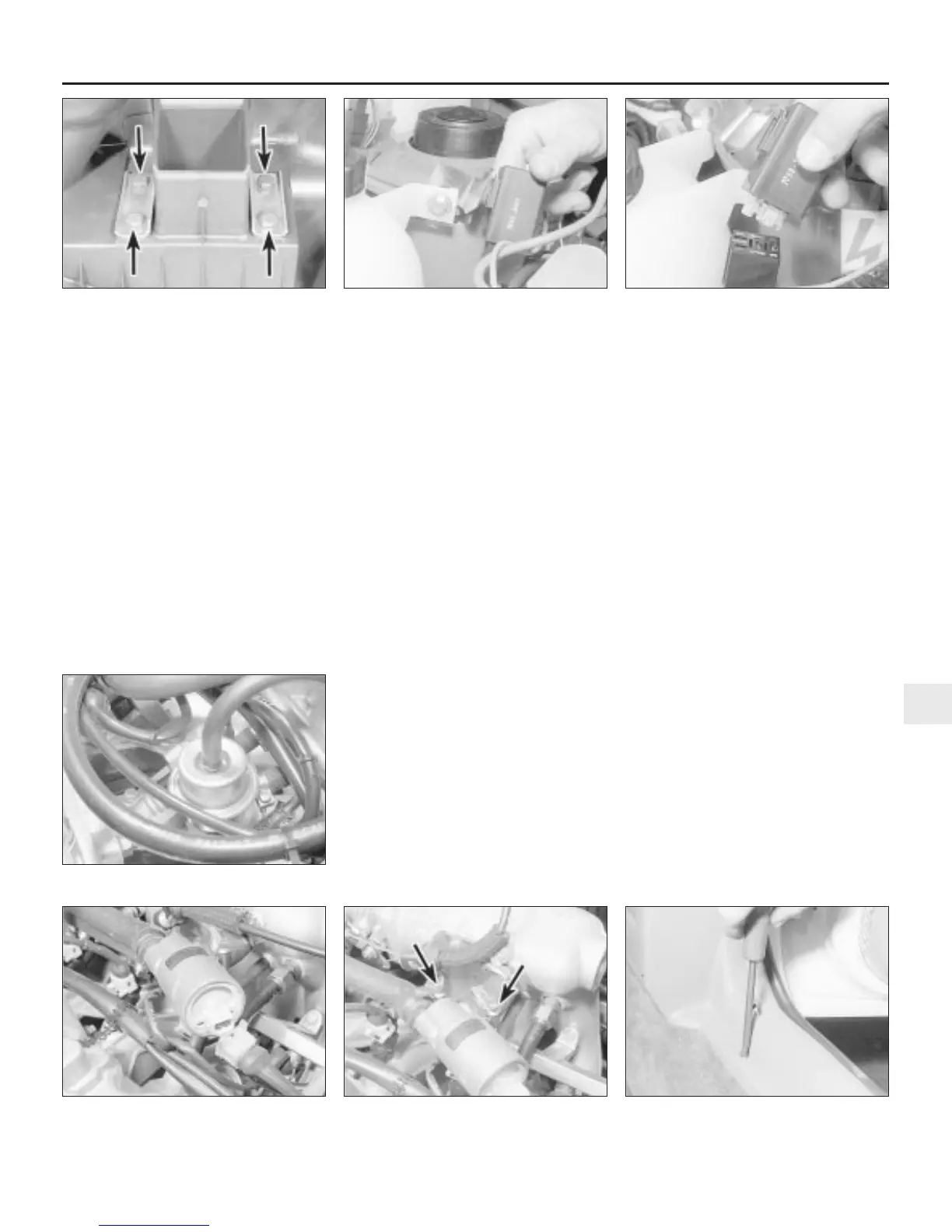
12.14 Airflow meter securing bolts
(arrowed)
12.36a Removing the control relay and
bracket
12.36b Unplugging the control relay
12.38 Fuel pressure regulator
12.44a Disconnect the idle speed adjuster
multi-plug . . .
12.46a Remove the kick plate screws . . .12.44b . . . and the air hoses (arrowed)

 Loading...