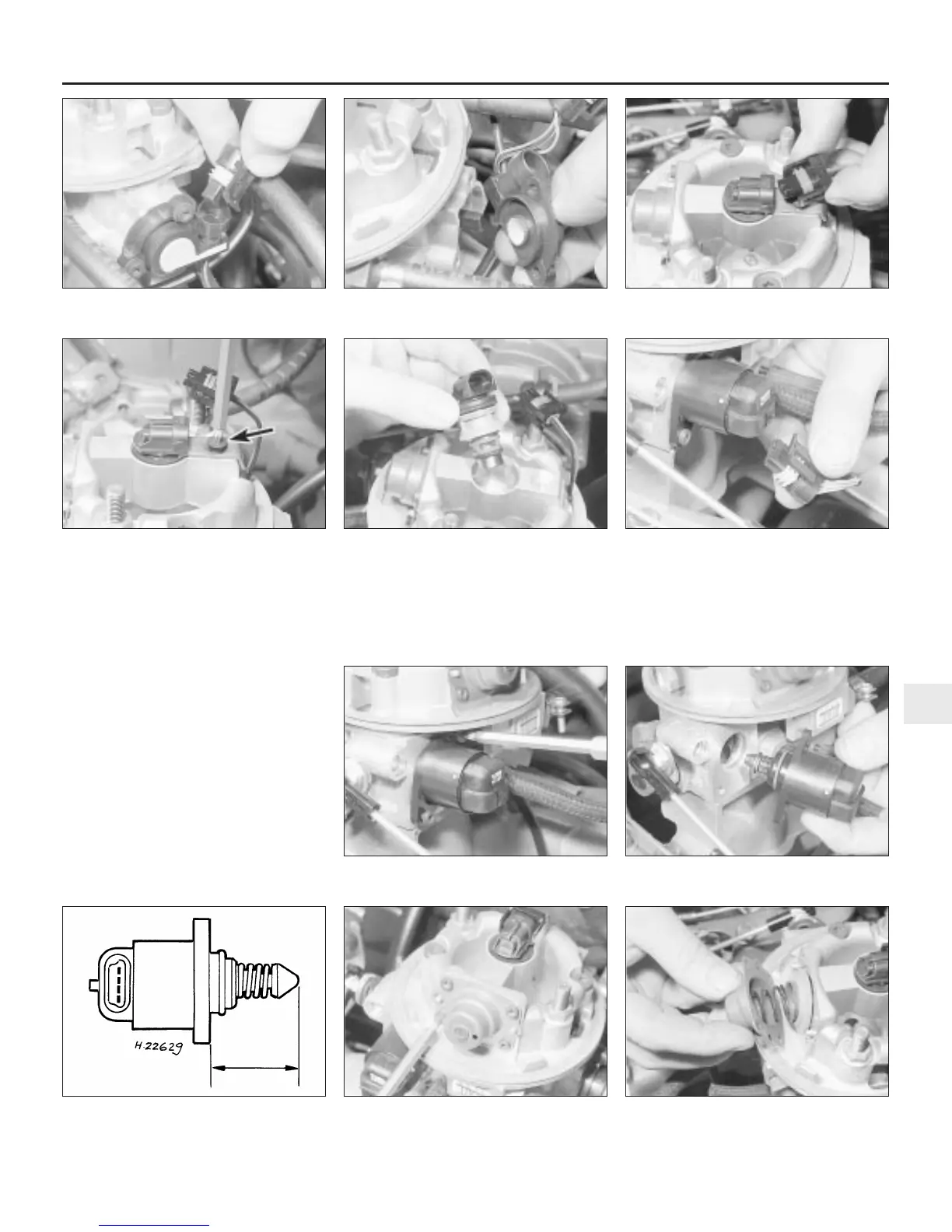
12 Refit in the reverse order of removal. To
avoid damaging the injector housing as the
motor unit is refitted, press the cone in against
its stop and check that the top of the cone to
the mating flange face is within 28 mm (see
illustration).
Throttle body/injector housing unit
13 Disconnect the wiring connectors from
the throttle body/injector housing.
14 Disconnect the operating rod, then
unscrew and remove the two retaining nuts
from the studs and carefully lift the throttle
body/injector housing from the inlet manifold.
Remove the gasket and clean the mating
surfaces.
15 Refit in the reverse order of removal, but
be sure to fit a new gasket between the
manifold and the throttle body/injector unit.
Tighten the retaining nuts to the specified
torque setting.
Pressure regulator
16 Prior to removal of the regulator unit, a
new diaphragm must be obtained as this must
be renewed whenever the cover is removed.
Release the pressure in the fuel system as
described in Section 6.
17 Undo the four retaining screws and
carefully withdraw the regulator unit cover,
spring and diaphragm (see illustrations).
18 Refit in the reverse order of removal.
Fuel and exhaust systems - fuel-injected models 4B•7
4B
11.3a Detach the wiring connector from
the throttle valve potentiometer
11.3b Throttle valve potentiometer removal 11.6a Disconnect the wiring connector . . .
11.6b . . . undo the retaining screw . . . 11.6c . . . and remove the injector
11.12 Idle air stepper motor cone tip-to-
flange distance should be as specified
11.17b . . . and remove the pressure
regulator cover, spring and diaphragm
11.17a Undo the retaining screws . . .
11.11b . . . undo the retaining screws . . . 11.11c . . . and remove the idle air stepper
motor
11.11a Detach the wiring connector . . .

 Loading...