11 Pull or twist out the vacuum piston spring
and needle of the carburettor first stage. Take
care not to bend the retaining bracket or
partial load needle.
12 If necessary, the partial load plunger may
be withdrawn by gripping its rod with a pair of
pliers.
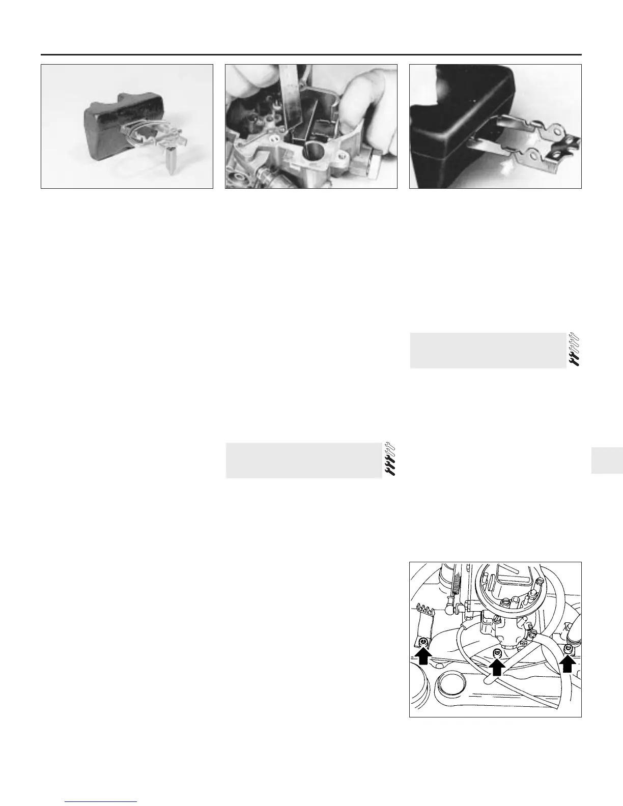
13 Remove the packing piece, float and
needle from the float chamber (see
illustration). Empty the fuel from the
chamber.
14 Note their location and unscrew the jets.
15 Extract the four retaining screws and
remove the throttle valve plate block.
16 Further dismantling is not recommended.
17 Clean all components and renew any that
are worn or damaged. If the throttle valve
plate spindle is worn then the complete
throttle block must be renewed. Clean jets
and passages with air pressure only; never
probe with wire or their calibration will be
ruined.
18 Obtain a repair kit which will contain all
the necessary renewable items, including
gaskets.
19 Reassembly is a reversal of dismantling,
but observe the following points.
20 When assembling the accelerator pump,
ensure that the check ball is correctly located.
21 Check that the needle valve spring is
correctly located on the float arm bracket.
There should be approximately 0.2 mm free
play between the spring and the bracket.
Correct if necessary by carefully bending one
item or the other.
22 Refit the float, needle valve and pivot
clips. Check the float level, with the gasket
fitted, by applying moderate finger pressure to
the float arms and pivot clip to close the
needle valve (see illustration). The top
surface of the float should be the specified
distance below the carburettor top flange.
23 Correct the float level if necessary by
carefully bending the float arms at the points
shown (see illustration).
24 When installing the cover to the
carburettor body, take care that the
accelerator pump plunger does not become
wedged.
25 Make sure that the breather screen is in
position.
26 Check that the bi-metallic spring of the
automatic choke engages positively with the
choke valve plate spindle arm.
27 Check the operation of the throttle valve
plate lever. Remember that the secondary
valve plate does not open until the primary
valve plate has opened by two-thirds of its
travel. The secondary throttle valve plate will
not open until the choke valve plate is fully
open after the engine has reached operating
temperature.
28 Carry out those checks and adjustments
in Section 15 which can be performed with
the carburettor on the bench.
29 After refitting, set the idle speed and
mixture, (Chapter 1), then carry out any
adjustments outstanding from Section 15.
Manual choke type
30 The operations are very similar to those
described in the preceding paragraphs, but
the references to automatic choke
components should be ignored.
Removal
1.2 litre models
1 The manifold may be removed with or
without the carburettor. In either case, refer to
Section 18 and follow the steps preparing for
carburettor removal.
2 Disconnect the brake servo vacuum hose.
3 Remove the three screws which secure the
manifold to the cylinder head (see
illustration).
4 Remove the manifold and recover the
gasket.
1.3, 1.4 and 1.6 litre models
5 Drain the cooling system, as described in
Chapter 1.
6 Remove the alternator, as described in
Chapter 5.
7 Release the coolant pipe from the inlet
manifold and clutch housing.
8 On 1.3 models, disconnect the coolant
temperature gauge lead.
9 Refer to Section 18 and either remove the
carburettor, or follow the steps preparing for
carburettor removal.
10 Disconnect the brake servo vacuum hose.
11 Remove the securing nuts and withdraw
the manifold. Recover the gasket.
Refitting
12 Refit in the reverse order to removal, using
a new gasket. Tighten the manifold nuts
progressively to the specified torque. On 1.3,
1.4 and 1.6 litre models refill the cooling
system and adjust the alternator drivebelt, as
described in Chapter 1.
Removal
1.2 litre models
1 Raise and securely support the front of the
car (see “Jacking and Vehicle Support”).
2 From under the car, separate the
manifold-to-downpipe joint by removing the
two bolts and recovering the tension springs.
3 Remove the air cleaner, as described in
Section 3.
4 Remove the six bolts which secure the
exhaust manifold to the cylinder head.
Remove the manifold and recover the gasket.
1.3, 1.4 and 1.6 litre models
5 Remove the air cleaner, as described in
Section 3. Also remove the hot air shroud;
noting how its sections fit over the manifold.
25 Exhaust manifold - removal
and refitting
24 Inlet manifold - removal and
refitting
Fuel and exhaust systems - Carburettor models 4A•19
4A
23.23 Float adjustment points (arrowed)
24.3 Three screws (arrowed) securing inlet
manifold - 1.2 litre models
23.22 Measuring the float level23.13 Float and needle valve

 Loading...