Removal
1 Slacken the front wheel bolts, raise and
support the vehicle (see “Jacking and Vehicle
Support”) and remove the front wheel.
2 Remove the split pin and undo the
driveshaft retaining nut (see Chapter 8 for
details). Remove the nut and washer.
3 Unbolt the brake caliper and tie it up out of
the way so that the hydraulic hose is not
strained (See Chapter 9 for details).
4 Disconnect the tie-rod and control arm
balljoints using a balljoint separator.
5 Push the driveshaft out of the hub and tie it
up out of the way (see Chapter 8). Remember
that the vehicle must not be moved on its
wheels without the hub bearing being clamped.
6 Undo the two securing nuts from the
suspension turret and remove the strut
downwards.
Refitting
7 Commence refitting by offering the strut to
the turret. Secure it with new self-locking
nuts, tightened to the specified torque.
8 Lubricate the driveshaft splines and pass
the driveshaft into the hub. Fit a new washer
and castellated nut, but only tighten the nut
finger tight at this stage.
9 Reconnect the control arm balljoint. Tighten
the pin nut to the specified torque and secure
it with a new split pin.
10 Reconnect the tie-rod balljoint. Fit a new
self-locking nut and tighten it to the specified
torque.
11 Clean out the brake caliper mounting bolt
holes, then refit the caliper and secure with
new bolts coated with thread locking
compound. Tighten the bolts to the specified
torque (see Chapter 9 Specifications).
12 Tighten the driveshaft nut (see Chapter 8).
13 Refit the roadwheel, lower the vehicle and
tighten the wheel bolts.
1 Remove the suspension strut (Section 2).
2 Remove the securing screw and take off
the brake disc.
3 Support the steering knuckle and press or
drive out the hub. Alternatively, draw off the
hub by screwing two wheel bolts onto
progressively thicker packing pieces (see
illustrations).
3 Front hub bearings - renewal
2 Front suspension strut -
removal and refitting
10•4 Suspension and steering
3.3b Hub removed from the carrier3.3a Removing the hub from the carrier
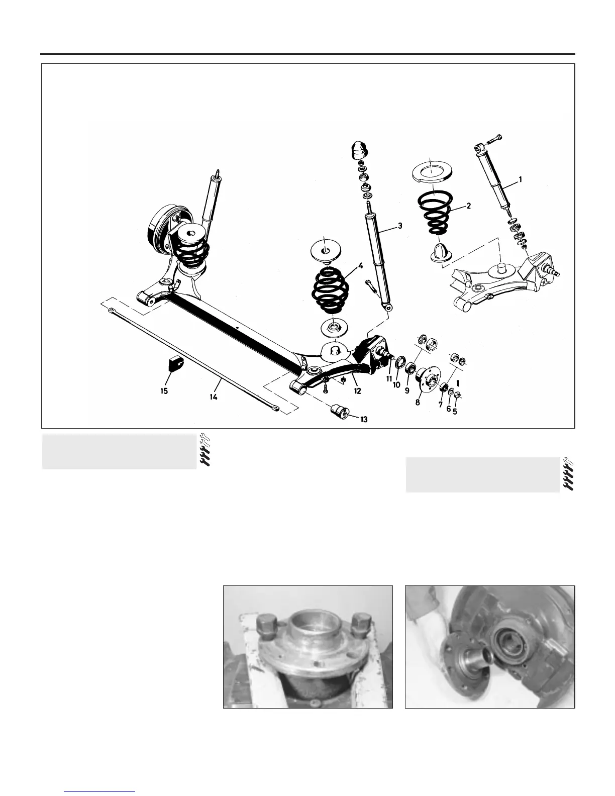
1.2 Exploded view of rear suspension components
1 Shock absorber (Estate)
2 Spring*
3 Shock absorber (Hatchback)
4 Spring*
5 Hub nut
6 Thrustwasher
7 Outer bearing
8 Hub
9 Inner bearing
10 Oil seal
11 Stub axle
12 Axle arm
13 Axle arm bush
14 Anti-roll bar
15 Rubber damper
*Typical - alternative type may be fitted


 To Next Page