- 23 -
optek-Manual--1004-2003-02--AF45-US-2011-01-04
www.optek.com
Connection to converter C 4000
Tool • Screw driver
To be able to allocate the end splices unequivocally to the terminals of the
converter, each end splice is marked with the number of the correct terminal:
Detector cable to sensor
1 = white (A1) 2 = brown (A2) 5 = black (A5)
Detector cable to sensor (reference channel)
3 = white (C3) 4 = brown (C4) 5 = black (C5)
Lamp cable to sensor
6 = white or blue (6) 7 = brown (7)
Caution!
Lamp voltage must be adjusted to the cable length in order to compensate
voltage loss in the cable. Too low lamp voltage can lead to wrong measuring
results. Too high lamp voltage reduces the life of the lamp module considerably.
Follow the instructions in the instruction manual of the converter. During
operation, voltage at the UV lamp is 7.0 V.
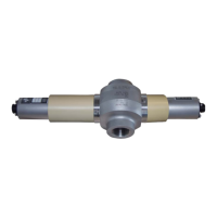
Tab. 11 Connections
Number of
sensors
sensor type
Detector input connection of the
converters
Lamp
output
Cable set stan-
dard length up to
C4101
C4121
C4151
C4201
C4221
C4251
C4202
C4222
C4252
C4322
C4352
C4422
C4452
1 sensor
AF45
A / C
A / C
A / C
A / C
E
100 m / 328 ft.
*
*. Cable sets length > 100 m (328 ft.) on request.
2 sensors
AF45
AF16
A / C
B
A / C
B
E
F
100 m / 328 ft.*
2 sensors
AF45
AS16 / AS16-BT
A / C
B
A / C
B
E
F
100 m / 328 ft.*
50 m / 164 ft.
2 sensors
AF45
AS56
A / C
B
A / C
B
E
F
100 m / 328 ft.*
50 m / 164 ft.
2 sensors
AF45
AF45
A / C
B / D
E
F
100 m / 328 ft.*
2 sensors
AF26
AF45
A / C
B / D
E
F
100 m / 328 ft.*
2 sensors
AF45
TF16
A / C
B / D
E
F
100 m / 328 ft.*
3 sensors
2 x AS56
AF45
A / C
B / D
E
F
50 m / 164 ft.
100 m / 328 ft.*