Maintenance
- 30 -
optek-Manual--1004-2003-02--AF45-US-2011-01-04
www.optek.com
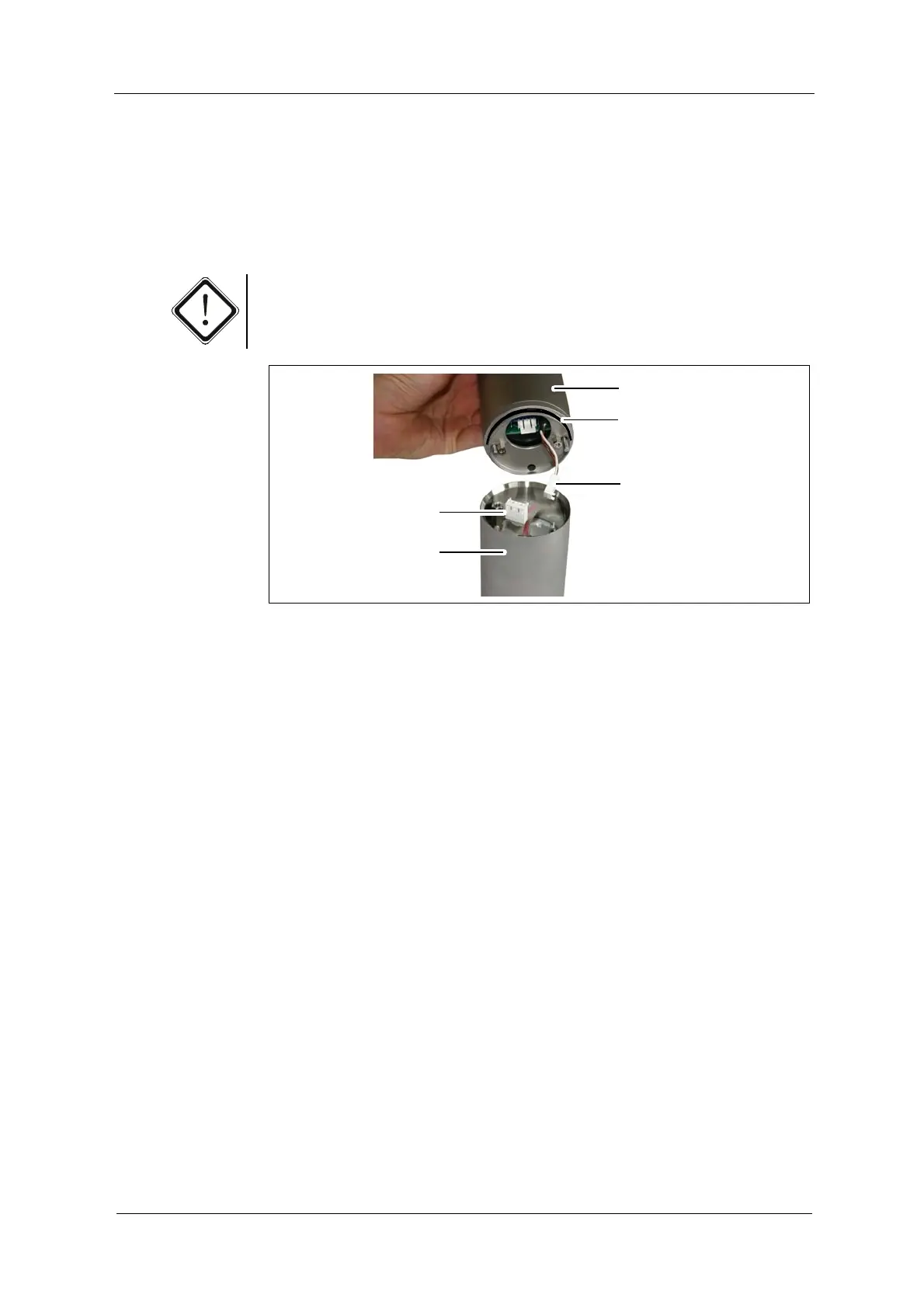
14. Check if the O-Ring (3, fig. 26) on the high voltage power supply is fitted
correctly. Replace it if necessary.
15. Connect the 2-pin connector (36, fig. 26) to the lamp module and the 3-pin
connector (35, fig. 26) to the reference detector. The connectors have to
audibly lock into place.
Caution!
If using a sensor AF46, make sure to connect both reference detectors as found.
Fig. 26 Mounting high voltage power supply, as shown with sensor AF45
16. Place the high voltage power supply on the optical housing OH2.
The pins at the edge of the high voltage power supply have to slide into the
drill holes of the housing.
17. Check the O-Rings of the screws and replace them if necessary. Fasten the
screws.
18. Re-connect the sensor cable.
19. Switch on the measuring system.
20. Follow the instructions given in chapter 9.4, page 32.